Method for configuring an optical network

a technology of optical networks and optical networks, applied in the field of optical networks, can solve the problems of unfavorable network planning, unfavorable network planning, and inability to simulate, plan or provision a transport network, and achieve the effect of wasting computing time and complexity

Inactive Publication Date: 2014-12-09
TELECOM ITALIA SPA
View PDF11 Cites 3 Cited by
  • Summary
  • Abstract
  • Description
  • Claims
  • Application Information

AI Technical Summary

Benefits of technology

[0025]On the opposite side of the “detail scale”, the layered graph replicates the network physical topology in as many planes as the number of wavelengths per fiber. Nodes are replicated in respective images, one per plane. Vertical links connecting images of the same node represent wavelength conversions and are created only for nodes having suitable converters. In a multi-fiber network, a number of planes equal to the number of fibers by the number of networks F×W is adopted, thus creating a number of vertical links to represent space switching. The layered graph model has the advantage of being able to store detailed information about wavelength assignment. Routing, fiber and wavelength assignment can be carried out jointly, thus achieving heuristic RWFA solutions very close to the optimal ones. Wavelength continuity constraint can be enforced and partial or limited wavelength conversion cases can be represented.
[0030]The latter drawback could be solved by introducing node splitting for taking into account of switching weights. With node splitting, a node is split into a set of images and new arcs are created to represent internal connections, assigning them suitable weights that describe different switching “costs”. However, the Applicants remark that node splitting also implies some disadvantages: node splitting is a pure mathematical tool, i.e. the created arcs do not correspond to any actual physical link that could be identified by an address or a name appearing in the physical topology. Moreover, as the node size gets larger a huge number of new objects (growing as the square of the node size) should be created: the presence of a high number of node images, treated by the heuristic (e.g. shortest-path) algorithms as regular nodes, greatly increments the number of steps and the quantity of information that has to be stored and updated during simulation, planning, or provisioning, resulting in huge complexity and computing time.
[0031]According to the Applicants, there is a need of a network model being able to map network elements of the physical topology of a network onto a graph representation in a flexible manner, in which the detail level could be scaled according to the actual needs, so as to limit, case by case, the complexity of the necessary calculation and / or the amount of memory occupation and / or CPU time.

Problems solved by technology

The Applicants remark that the known network models in all the cases found in literature are not very flexible for the main reason that in them the network is internally represented with a constant level of detail in all its the regions and all its elements.
This leads to the drawback that sometimes network planning is carried out with an unnecessary huge complexity of calculation, memory occupation and / or computing time.
On the other hand, some other times the model does not allow to simulate, plan or provision a transport network in many possible scenarios.
Multiplicity (i.e. the maximum number of connections that can be hosted by an edge) is equal to the product of the number of fibers per link F by the number of wavelengths per fiber W. The Applicants remark that this model is very limited, since it is not able to represent wavelength information.
Wavelength and fiber assignment can never be done jointly with routing.
Furthermore, in case of WP networks, in which wavelength conversion cannot be performed, the wavelength continuity constraint cannot be enforced.
However, the Applicants remark that a number of drawbacks can be identified with regards to the layered-graph model.

Method used


Image

  • Method for configuring an optical network
  • Method for configuring an optical network
  • Method for configuring an optical network

Examples


Embodiment Construction

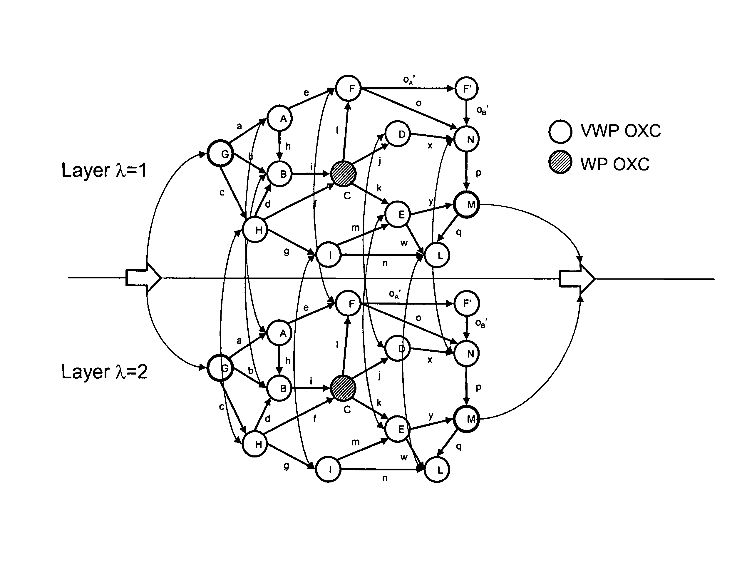
[0064]The model that will be disclosed in the following can exemplarily be applied to an OTN / ASON (Optical Transport Network / Automatic Switched Optical Network) network scenario, possibly managed by the GMPLS (Generalized Multi Protocol Label Switching) protocol. However, it is applicable, in general, to problems in which network resources have to be assigned to any kind of traffic flow. More precisely, it is best suited to cases in which network resource assignment can be solved by graph-based algorithms. Typical applications might comprise: MPLS (Multi Protocol Label Switching), SDH / Sonet (Synchronous Digital Hierarchy / Synchronous Optical Network) network design, IP-TE (Internet Protocol / Traffic Engineering) routing, ATM (Asynchronous Transfer Mode) routing, PSTN (Plain Service Telephone Network) routing, ISDN (Integrated Service Digital Network) routing, Frame-Relay routing, X.25 routing.

[0065]With exemplary reference to a WDM network, the setup of one or more lightpaths on a WDM...


PUM


Abstract

A network model for the planning and / or the provisioning of traffic flows in a communication network includes nodes interconnected with each other by links according to a given network topology. The network model uses a graph defined by arc objects storing information related to both the links and adjacent nodes thereof.

Description

CROSS REFERENCE TO RELATED APPLICATION[0001]This application is a national phase application based on PCT / EP2005 / 008590, filed Aug. 8, 2005.BACKGROUND OF THE INVENTION[0002]The present invention relates a method for simulating, planning and / or provisioning traffic flows in communication networks, particularly optical networks, more particularly optical networks employing wavelength division multiplexing (WDM).[0003]Transport networks are typically wide area networks that provide connectivity for aggregated traffic streams. Modern transport networks increasingly employ optical technology, and particularly wavelength division multiplexing (WDM) technology, to utilize the vast transmission bandwidth of optical fiber. WDM is based on transmission of data over separate wavelength channels on each fiber. Presently, WDM is mainly employed as a point-to-point transmission technology. In such networks, optical signals on each wavelength are converted to electrical signals at each network nod...

Claims


Application Information

Patent Timeline
Patent Type & Authority Patents(United States)
IPC IPC(8): H04L12/721H04L12/801H04L12/28H04L12/26H04L12/833H04L47/31
CPCH04L45/12H04L45/123H04L47/10H04J14/0267H04L45/124H04L47/31H04L47/39H04L47/29
Inventor MAIER, GUIDO ALBERTODE PATRE, SIMONEFERRARIS, GIUSEPPE
Owner TELECOM ITALIA SPA
Why Eureka
Try Eureka