
Apparatus and method for time alignment of an envelope tracking power amplifier

a power amplifier and envelope tracking technology, applied in the direction of synchronising signal speed/phase control, digital transmission, baseband system details, etc., can solve the problems of large amount of silicon resources, high computational complexity of ta algorithms, and difficulty in achieving cost-effective dsp implementation

Active Publication Date: 2014-12-09
SAMSUNG ELECTRONICS CO LTD
View PDF5 Cites 10 Cited by
  • Summary
  • Abstract
  • Description
  • Claims
  • Application Information

AI Technical Summary

Benefits of technology

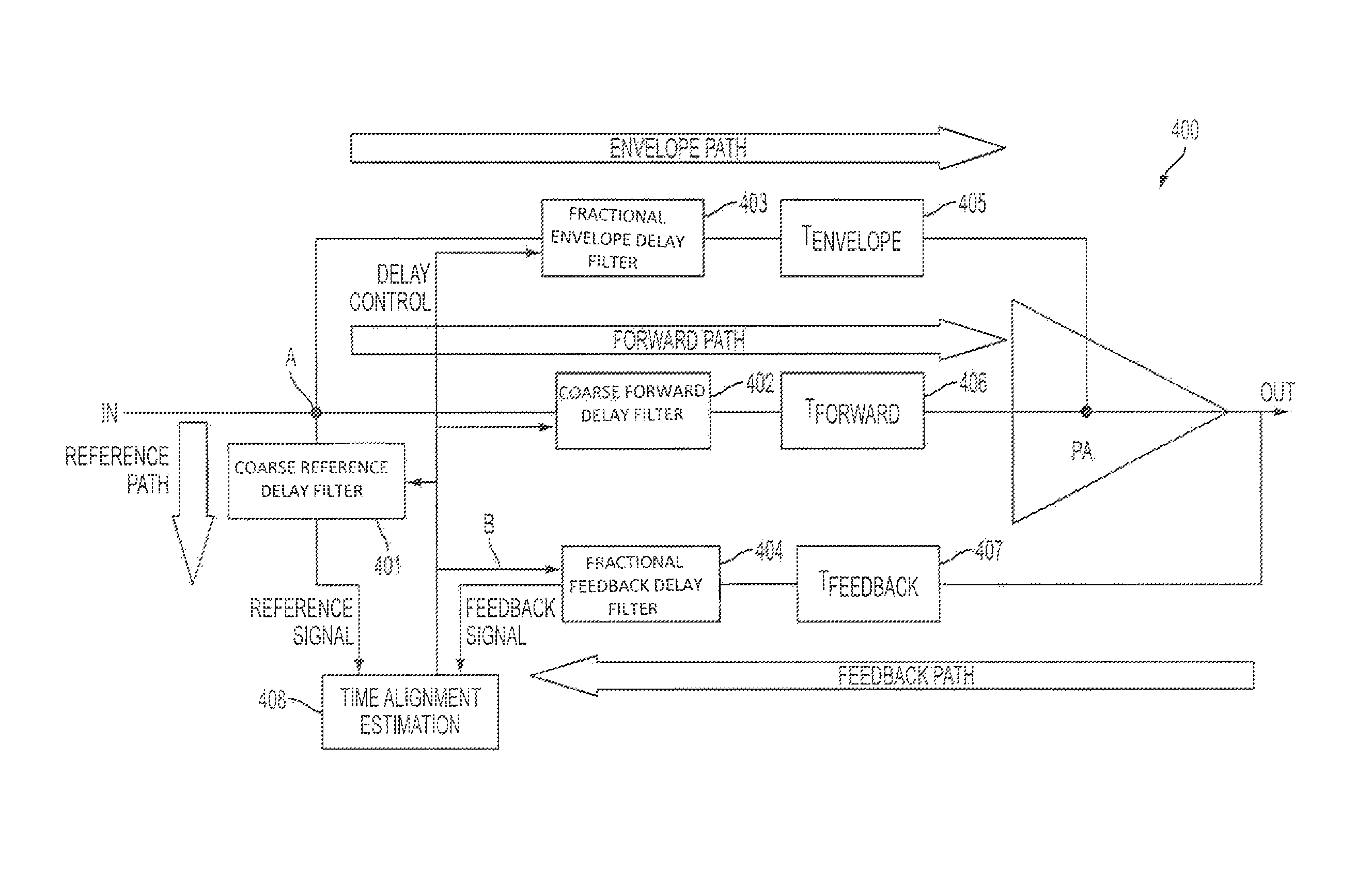
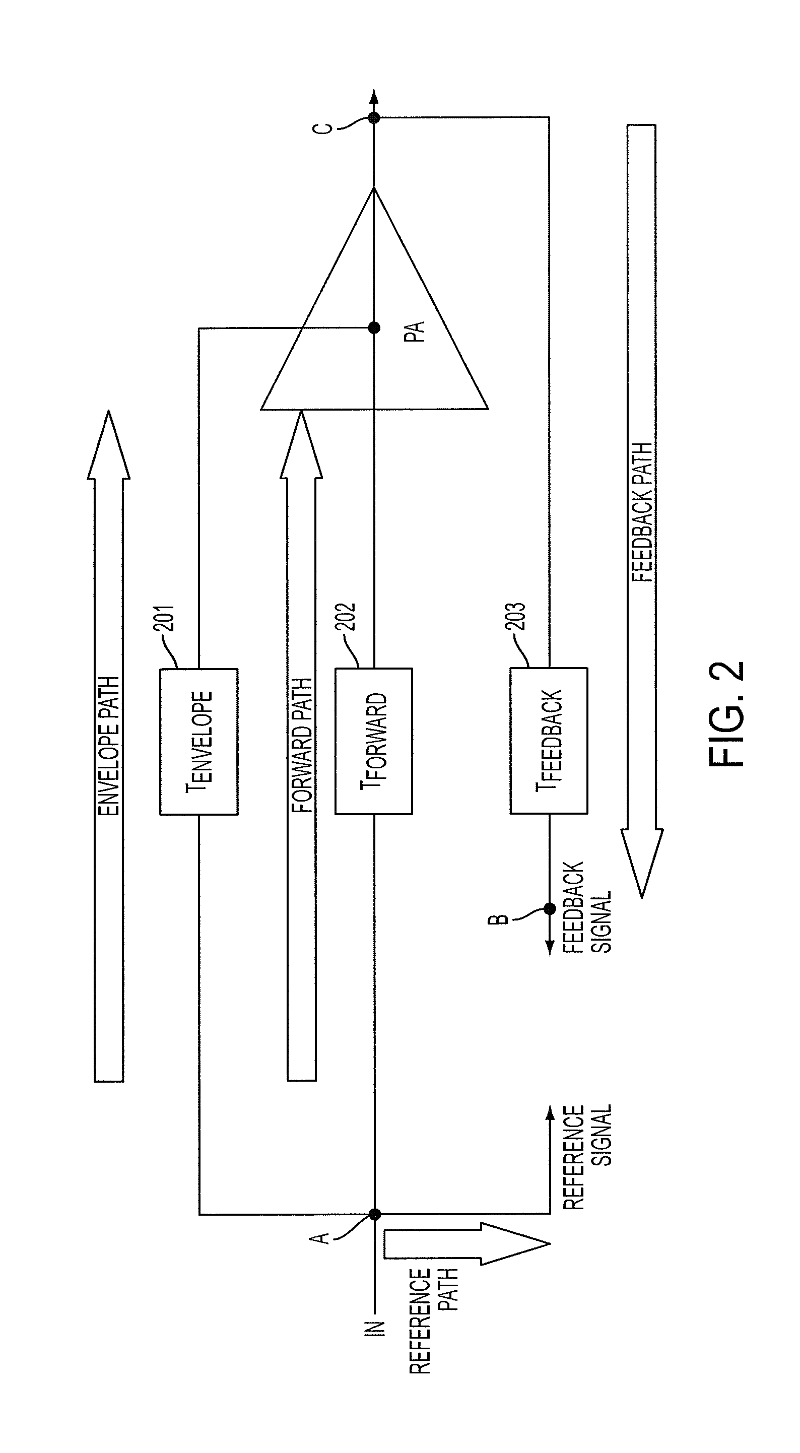
[0017]In accordance with another aspect of the present invention, an apparatus for an Envelope Tracking (ET) Radio Frequency (RF) Power Amplifier (PA) having an input signal, including a complex signal, that is propagated along a forward path of the ET RF PA having a forward path delay, a reference signal that is propagated along a zero-delay reference path of the ET RF PA, and a feedback signal, extracted from an output node of the ET RF PA, propagating along a feedback path having a feedback path delay is provided. The apparatus includes a fast convolution unit for receiving the reference signal and the feedback signal, fore extracting respective envelopes of the reference signal and the feedback signal, for generating a cross-covariance vector for the reference signal envelope and the feedback signal envelope, a delay estimation unit for receiving the cross-covariance vector from the fast convolution unit, for determining peak values of the cross-covariance vector, for performing a fine time delay estimation, and for generating time delay settings according to the fine time delay estimation, and delay filters respectively delaying a timing of the reference signal and the feedback signal according to the generated time delay settings.

Problems solved by technology

TA algorithms present considerable challenges towards achieving a cost-effective DSP implementation.
The TA algorithms are based on cross-correlation / cross-covariance techniques, and thus, the TA algorithms present a high computational complexity require large amounts of silicon resources of FPGAs or large amounts of computation time of the DSP-CPU.
However, such a range for the time mismatch sensitivity requires a high time resolution.
The processing of the large data arrays resulting from the high time resolution makes the implementation of the TA algorithm impractical.
However, in the off-line technique, consideration is not given to temperature variations during the real time operation.
In addition, if any variant from the off-line technique is suitable for on-line operation, it requires processing the cross-correlation estimation two times, which substantially increases computation time.
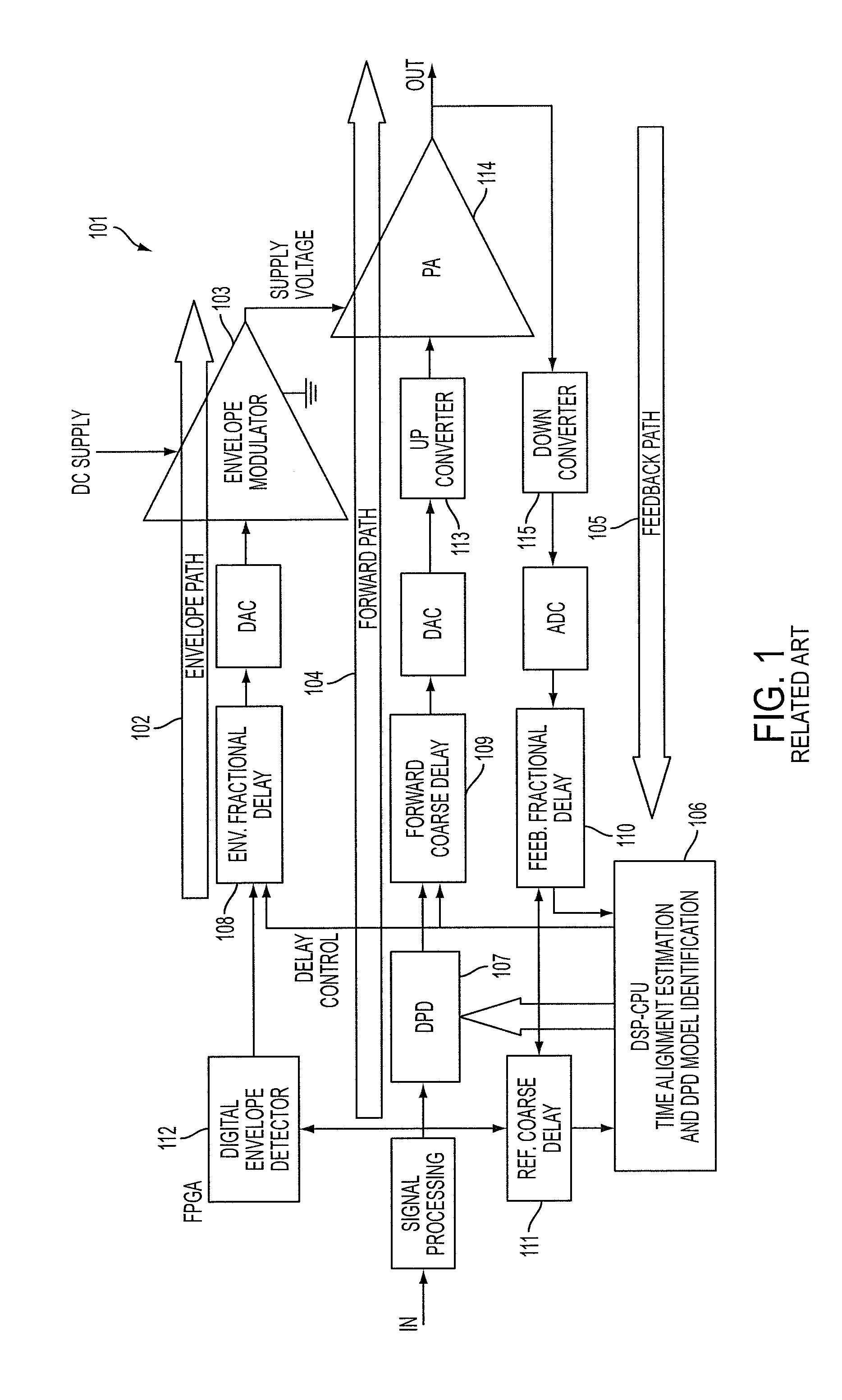
However, an Adjacent Channel Leakage Ratio (ACLR) at the output of the PA using ET is highly sensitive to a delay mismatch between the envelope path and the forward path to the PA.
However, the time mismatch between the reference signal and the feedback signal does have an effect on the DPD modeling for the DPD model located in the DPD block of the PA using ET.
A time mismatch included in the modeling process affects the characteristic of the distortion generated by the DPD model which is used to cancel distortion from the PA nonlinearity.
However, when the data arrays to be used by the TA algorithm are too large for the on-chip memory, the data arrays need to be constantly moved from being stored in the on-chip memory to being stored in an off-chip external memory.
The data arrays used for a highly accurate cross-correlation method having a large number of samples may be too large to store on the on-chip memory, and thus may be subject to being constantly moved from the on-chip memory to the off-chip memory during a DSP operation.

Method used


Image

  • Apparatus and method for time alignment of an envelope tracking power amplifier
  • Apparatus and method for time alignment of an envelope tracking power amplifier
  • Apparatus and method for time alignment of an envelope tracking power amplifier

Examples


Embodiment Construction

[0030]The following description with reference to the accompanying drawings is provided to assist in a comprehensive understanding of exemplary embodiments of the invention as defined by the claims and their equivalents. It includes various specific details to assist in that understanding but these are to be regarded as merely exemplary. Accordingly, those of ordinary skill in the art will recognize that various changes and modifications of the embodiments described herein can be made without departing from the scope and spirit of the invention. In addition, descriptions of well-known functions and constructions are omitted for clarity and conciseness.

[0031]The terms and words used in the following description and claims are not limited to the bibliographical meanings, but, are merely used by the inventor to enable a clear and consistent understanding of the invention. Accordingly, it should be apparent to those skilled in the art that the following description of exemplary embodime...


PUM


Abstract

An apparatus and method for a Time Alignment (TA) operation used by an Envelope Tracking (ET) Radio Frequency (RF) Power Amplifier (PA) that amplifies RF signals are provided. The ET RF PA has an input signal including complex, reference, and feedback signals. The apparatus includes a fast convolution unit for receiving the reference signal and the feedback signal, fore extracting respective envelopes of the reference signal and the feedback signal, for generating a cross-covariance vector for the reference signal envelope and the feedback signal envelope, a delay estimation unit for receiving the cross-covariance vector from the fast convolution unit, for determining peak values of the cross-covariance vector, for performing a fine time delay estimation, and for generating time delay settings according to the fine time delay estimation, and delay filters respectively delaying a timing of the reference signal and the feedback signal according to the generated time delay settings.

Description

BACKGROUND OF THE INVENTION[0001]1. Field of the Invention[0002]The present invention relates to an apparatus and method for time alignment of an Envelope Tracking (ET) Radio Frequency (RF) Power Amplifier (PA). More particularly, the present invention relates to an apparatus and method for a time alignment operation used by a ET RF PA that amplifies RF signals.[0003]2. Description of the Related Art[0004]In recent years, the use of mobile communications using wireless communication networks has become widespread, thus, increasing a demand for faster, higher bandwidth, and more efficient wireless communication networks. The wireless communication networks communicate using RF signals propagated in the wireless communication networks that may be divided into communication cells. The communication cells, providing wireless communication to mobile devices located in respective coverage areas of the communication cells, may include Base Stations (BSs) that include RF transmitters and Di...

Claims


Application Information

Patent Timeline
Patent Type & Authority Patents(United States)
IPC IPC(8): H04L25/17H03F1/26H04B1/16
CPCH03F3/19H03F1/0222H04L27/368H04L27/361H03F3/245H03F1/3247H04L7/04
Inventor JECKELN, ERNESTO, G.
Owner SAMSUNG ELECTRONICS CO LTD
Learn More