Horizontal auger garden tilling apparatus and method of use

a technology of horizontal auger and garden tilling, which is applied in the direction of tilling equipment, mechanical conveying drilling, spades, etc., can solve the problems of inability to effectively penetrate the afore described hard complexes or compacted soil, prior art powered augers have not provided an apparatus or method of use to hold the auger substantially or reasonably perpendicular to the soil surface, and the present art apparatuses purposely do not have substantially continuous flighting, so as to achiev

Inactive Publication Date: 2014-12-16
PROVINES WYNN
View PDF16 Cites 12 Cited by
  • Summary
  • Abstract
  • Description
  • Claims
  • Application Information

AI Technical Summary

Benefits of technology

[0016]The present art apparatus and method of use allows a user to easily lower the auger into the soil via tractor three point hitch lift arms or a lift mechanism of a movable carriage and with the locomotion provided by the tractor or movable carriage till the soil to a depth which is highly beneficial for optimum root growth

Problems solved by technology

Unfortunately, conventional garden tillers utilize rotating heads having tines which have a rotational axis substantially parallel with the surface plane of the soil.
The aforesaid conventional tillers cannot effectively penetrate the afore described hard complexes or compacted soil.
Unfortunately, an untilled subsurface layer limits the depth of plant root growth and forces a root formation which is more “pancake” shaped rather than the desirable root “ball” shape.
When plant roots are limited in the depth of soil penetration, so is the plant health and the fruit or vegetable producing capacity of the plant.
Conventional prior art powered auger systems are primarily utilized for post holes and have not anticipated or suggested a design or embodiment capable of movement through soil for tilling purposes.
That is, prior art powered augers have not provided an apparatus or method

Method used


Image

  • Horizontal auger garden tilling apparatus and method of use
  • Horizontal auger garden tilling apparatus and method of use
  • Horizontal auger garden tilling apparatus and method of use

Examples


Embodiment Construction

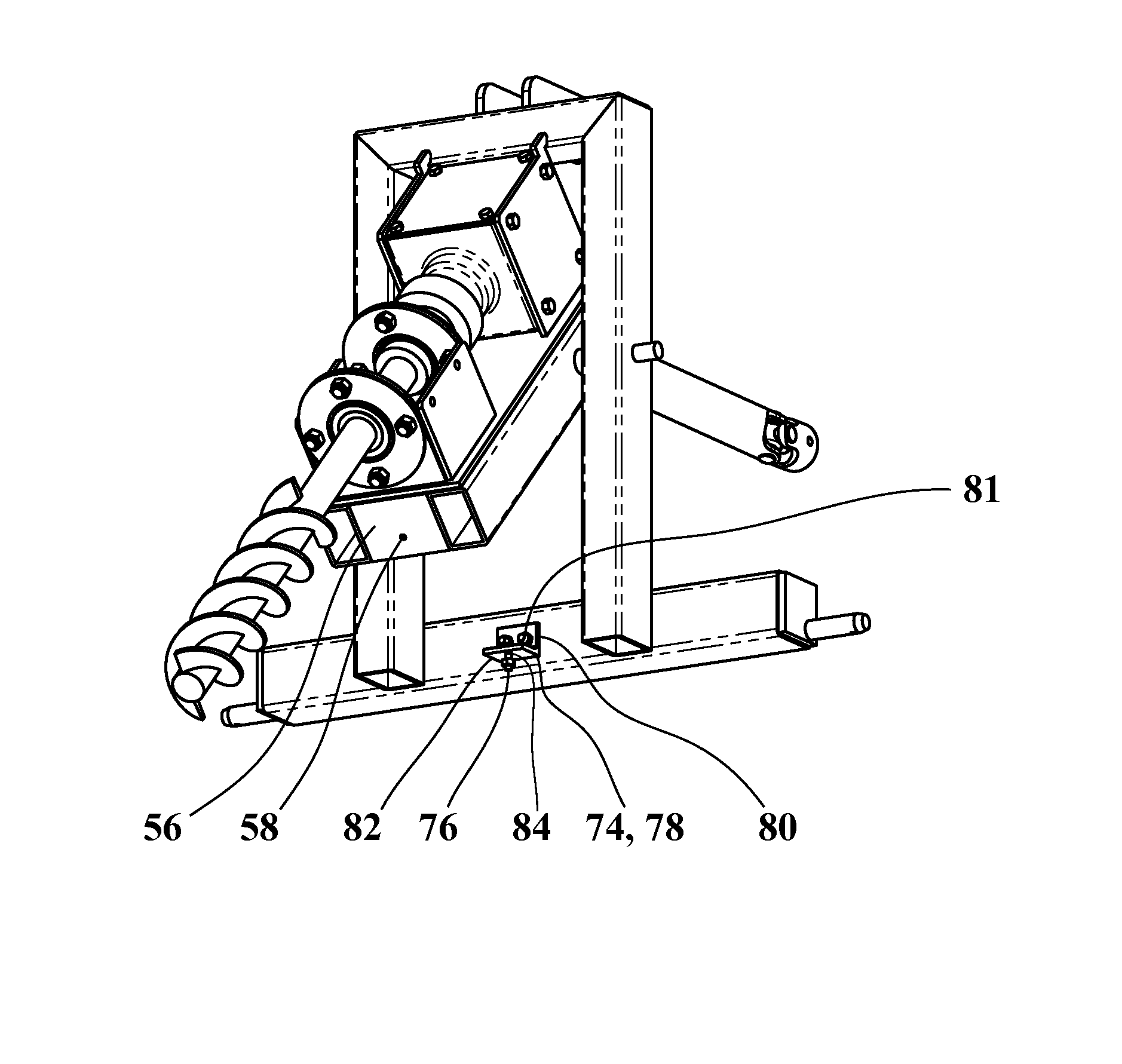
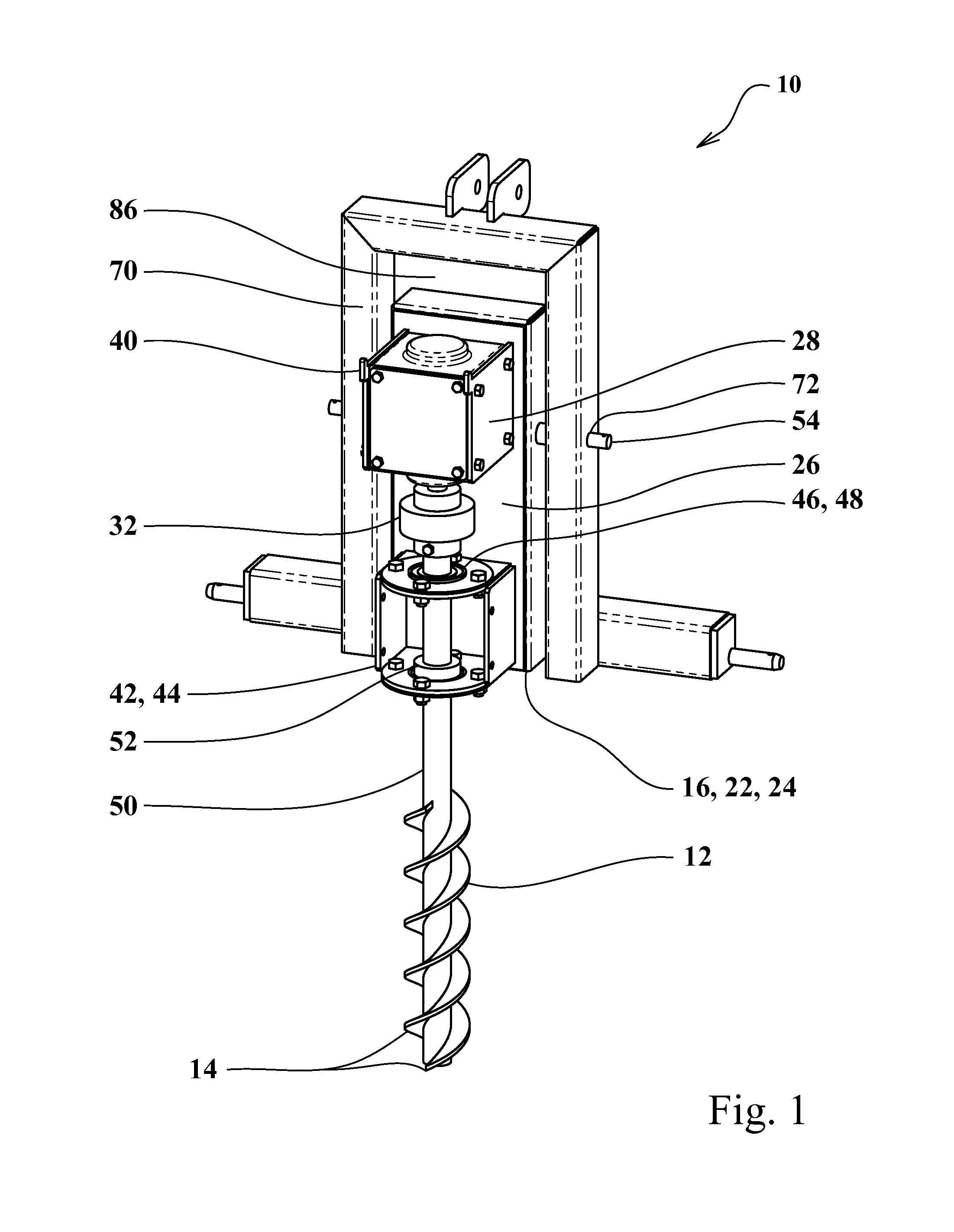
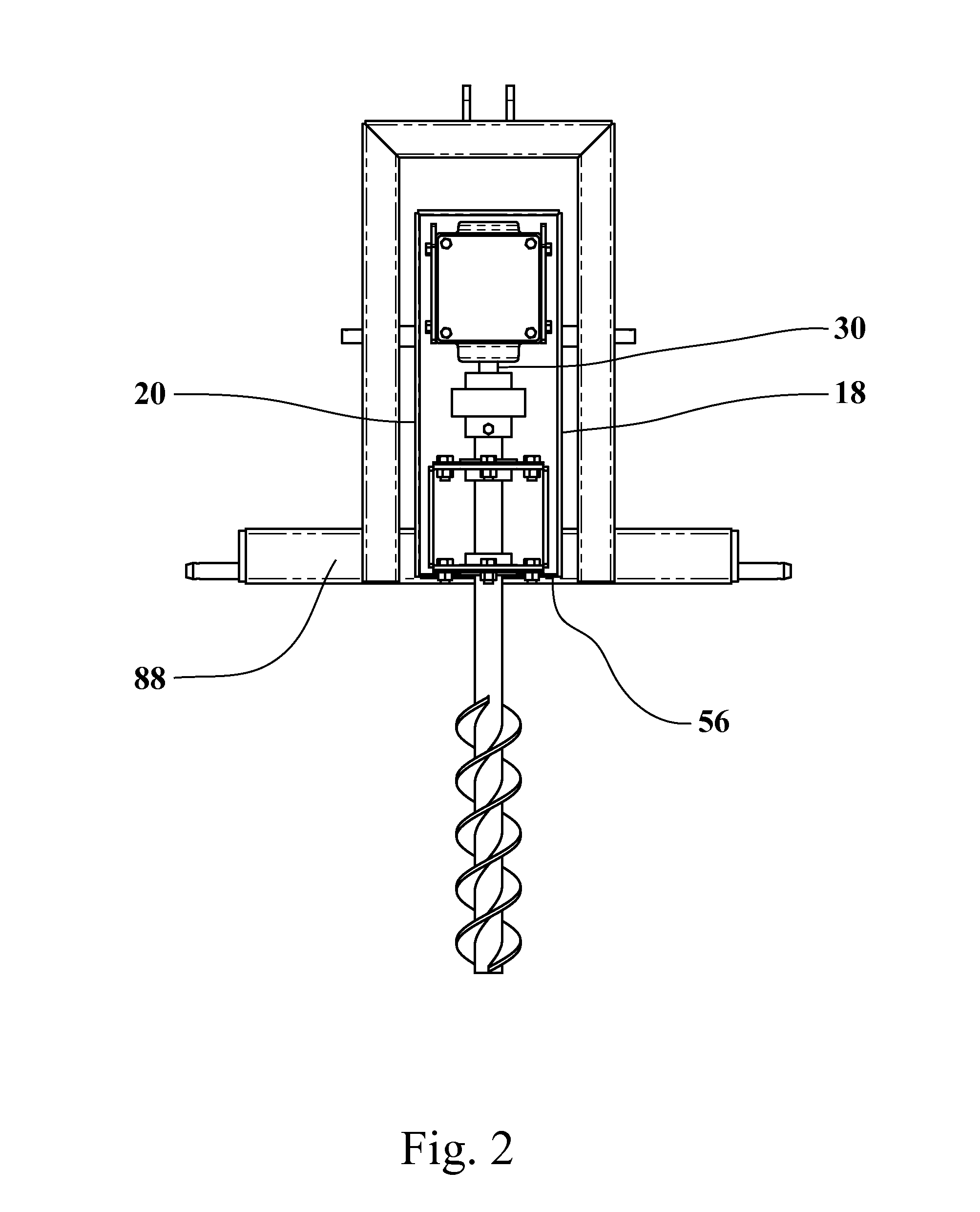
[0036]In accordance with the present invention, the first or preferred embodiment horizontal auger garden tilling apparatus 10 comprises a pivoting inner frame 16 onto which is mounted a gear box 28 having an output shaft 30 coupled with an auger shaft 50. The auger shaft 50 is rotationally held via a bearing mount assembly 42 between the gear box 28 and the flights 14 of the auger shaft 50. The bearing mount assembly 42 is secured with the inner frame 16 and holds one or more bearing assemblies 46 which allow the auger shaft 50 to rotate but limits any movement of the auger shaft 50 relative to the inner frame 16. The bearing mount assembly 42 may take a plurality of forms which are capable of holding the bearings 48 in a substantially fixed position relative to the inner frame 16. These include but are not limited to pillow block bearings, mounted bearings, flangette bearings, flanged bearings, pressed bearings, and sleeved bearings. For the preferred embodiment, the bearings 48 a...


PUM


Abstract

A horizontal auger garden tilling apparatus and method of use having an outer frame, an inner frame which pivots with said outer frame, and a rotating auger capable of tilling soil to depth which conventional tillers cannot begin to reach. The apparatus is moved and the method of use is performed via attachment with a tractor or other movable carriage which provides enough horizontal force to move the auger through the soil and provides auger rotational power. A trencher attachment prevents auger soil refilling and allows the apparatus and method of use to be utilized and performed in conjunction with trenching operations.

Description

[0001]This application claims priority of U.S. Provisional Patent Application #61 / 777,763, filed Mar. 12, 2013, entitled Horizontal Auger Garden Tilling Apparatus and Method of Use.BACKGROUND OF THE INVENTION[0002]The art of the present invention relates to powered garden tilling apparatuses and methods of use in general and more particularly to a powered auger apparatus and method of use which is horizontally moveable through the soil and which allows deep tilling of compacted and hardened soils. The present art method of use allows a user to loosen soil in a wide swath with a single pass to a depth which is well below the depths of conventional horticulture, agriculture, or gardening equipment. The apparatus and method of use is available for small or compact tractors and for a powered carriage or walk behind apparatus and allows a method of use which is easy, quick, and relatively effortless.[0003]As most gardeners are aware, the soil in a garden generally requires tilling prior ...

Claims


Application Information

Patent Timeline
IPC IPC(8): A01B33/06A01B33/08E02F5/04A01B49/02A01B33/10
CPCA01B33/106A01B33/06A01B49/025A01B33/087E21B7/005E21B7/024E21B7/02
Inventor PROVINES, WYNN
Owner PROVINES WYNN
Why Eureka
Try Eureka