
Sliding member, manufacturing method thereof, mechanical seal ring using sliding member and mechanical seal using mechanical seal ring

a technology of sliding member and manufacturing method, which is applied in the field of sliding member, can solve the problems of pore forming agent liable to aggregate, seal properties may rapidly deteriorate, etc., and achieve excellent sealing properties, excellent lubricating liquid holding performance, and excellent thermal conductivity

Active Publication Date: 2014-12-23
KYOCERA CORP
View PDF21 Cites 0 Cited by
  • Summary
  • Abstract
  • Description
  • Claims
  • Application Information

AI Technical Summary

Benefits of technology

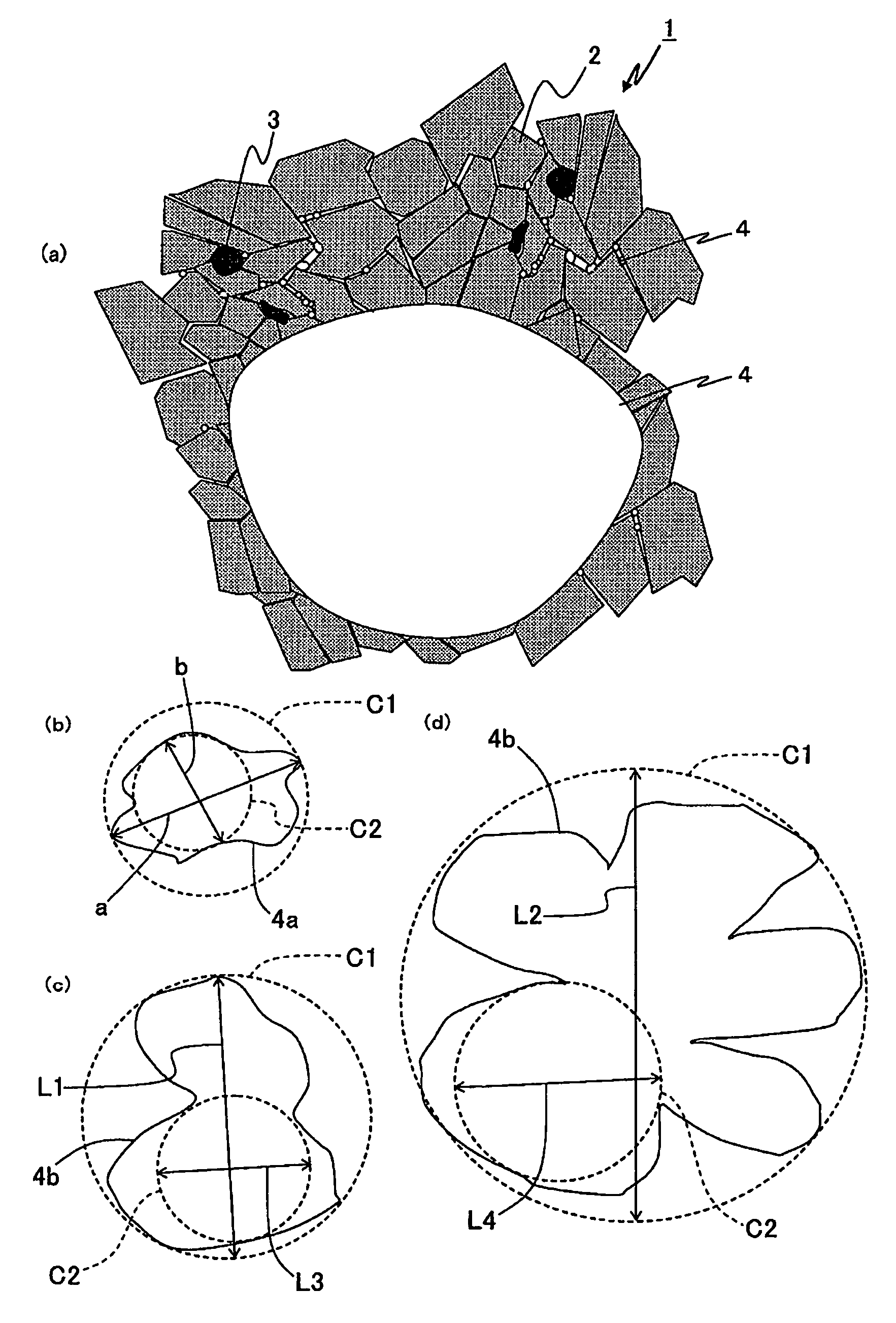
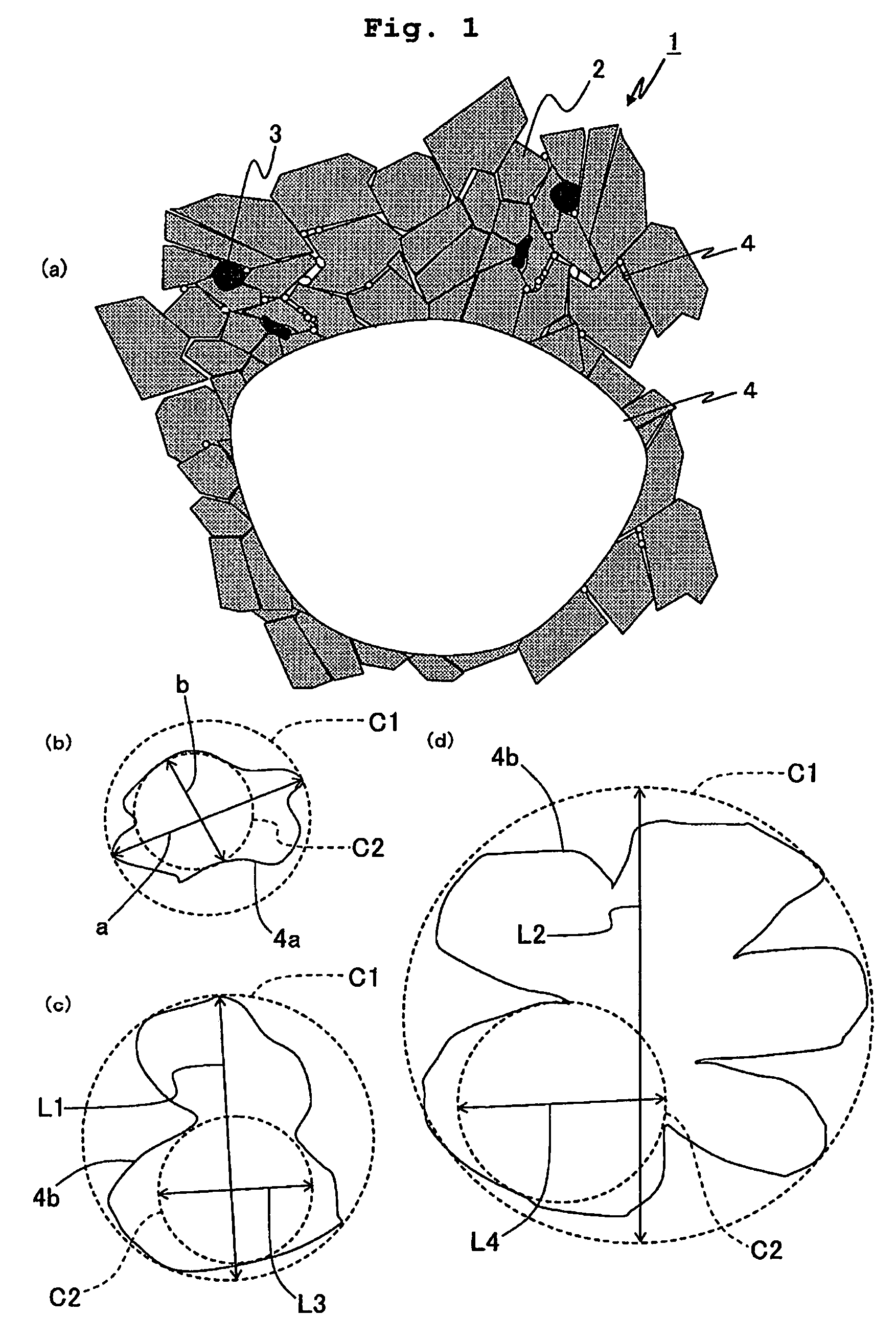
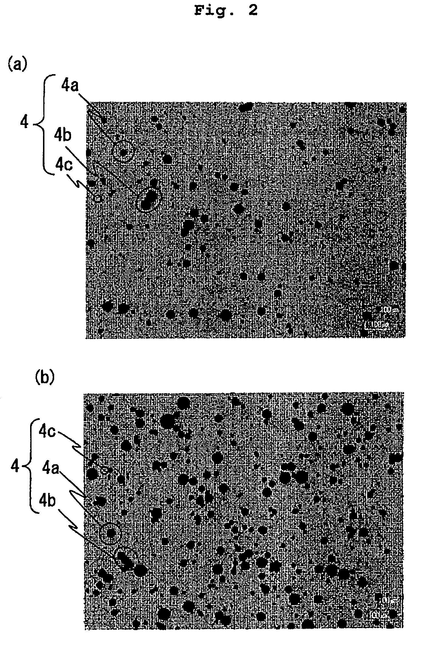
The present invention provides a sliding member, such as a mechanical seal ring, that can maintain excellent seal properties even in a continuous long-term use. It has excellent lubricating liquid holding performance, as well as thermal conductivity and thermal shock resistance. The sliding member has a sliding surface comprising a silicon carbide sintered body having a primary phase and a subphase, wherein the subphase has a different composition from the primary phase and contains boron, silicon and carbon. The ratio of pores in the sliding surface is60 % or more. This reduces very large pores that deteriorate seal properties, and also reduces communicating pores, which facilitates a long-term retention of seal properties.

Problems solved by technology

However, the pore forming agent is liable to aggregate.
Therefore, a long-term continuous use of the sliding member has caused the problem that seal properties may rapidly deteriorate because stress concentrates during sliding at the periphery of the contour forming the communicating pores, thus being susceptible to degranulation.

Method used


Image

  • Sliding member, manufacturing method thereof, mechanical seal ring using sliding member and mechanical seal using mechanical seal ring
  • Sliding member, manufacturing method thereof, mechanical seal ring using sliding member and mechanical seal using mechanical seal ring
  • Sliding member, manufacturing method thereof, mechanical seal ring using sliding member and mechanical seal using mechanical seal ring

Examples


example i

[0103]A predetermined amount of boron carbide powder was added to silicon carbide powder as a main ingredient, and suspension-polymerized non-crosslinked resin beads composed of phenol resin and polystyrene having the maximum diameter shown in Table 1 was added thereto as a pore forming agent. The pore forming agent having a roundness of 4 μm or less and a diameter of 12 to 75 μm was used in each sample. The pore forming agent was added at the ratio shown in Table 1, with respect to 100% by mass of the mixed powder of silicon carbide and boron carbide. Further, as a pore dispersing agent, polycarboxylic acid sodium was added and mixed at the ratio shown in Table 1, with respect to 100% by mass of the pore forming agent, thereby obtaining a raw material.

[0104]The obtained raw material was put into a ball mill and mixed for 48 hours to make slurry. As a molding additive, binder was added and mixed to the slurry, followed by spray drying, thereby obtaining a molding raw material compos...

example ii

[0125]Firstly, boron carbide powder, a pore forming agent, a pore dispersing agent and water, each having the amount of addition shown in Table 2, were added to silicon carbide powder, and put into a ball mill and mixed for 48 hours to make slurry. As a molding additive, binder was added and mixed to the slurry, followed by spray drying, thereby obtaining silicon carbide granules having a mean particle diameter of 80 μm.

[0126]As the above pore forming agent, suspension-polymerized non-crosslinked resin beads composed of previously ground polystyrene were used, which had a roundness of 4 μm or less and a diameter of 12 to 75 μm, and had the maximum diameter shown in Table 2. As the above pore dispersing agent, polycarboxylic acid sodium was used.

[0127]Subsequently, the mixed raw material was charged into a mold, and then pressed and molded at a pressure of 98 MPa in the thickness direction, thereby obtaining a molded body having a predetermined shape. The temperature of the obtained ...

example iii

[0144]Firstly, 2.5% by mass of boron carbide powder, a pore forming agent, a pore dispersing agent and water, each having the amount of addition shown in Table 3, were added to silicon carbide powder, and put into a ball mill and mixed for 48 hours to make slurry. As a molding additive, binder was added and mixed to the slurry, followed by spray drying, thereby preparing silicon carbide granules having a mean particle diameter of 80 μm.

[0145]As the above pore forming agent, suspension-polymerized non-crosslinked resin beads composed of previously ground polystyrene were used, which had a roundness of 4 μm or less and a diameter of 12 to 75 μm, and had the maximum diameter shown in Table 3. As the above pore dispersing agent, polycarboxylic acid sodium was used.

[0146]Subsequently, the mixed raw material was charged into a mold and pressed and molded at a pressure of 98 MPa in the thickness direction, thereby obtaining a molded body having a predetermined shape.

[0147]The temperature o...


PUM

PropertyMeasurementUnit
pore diameteraaaaaaaaaa

Abstract

A sliding member having a sliding surface comprising a silicon carbide sintered body having a primary phase comprising mainly silicon carbide, and a subphase having a different composition from the primary phase and containing at least boron, silicon and carbon. The ratio of pores having a roundness of 6 μm or less and a pore diameter of 10 to 60 μm with respect to all pores having a pore diameter of 10 μm or more in the sliding surface is 60% or more. This enables retention of good seal properties even in a long-term continuous use. The subphase in the silicon carbide sintered body is preferably granular crystal phases dotted among a plurality of the primary phases. This provides excellent lubricating liquid holding performance as well as excellent thermal conductivity and excellent thermal shock resistance properties.

Description

CROSS-REFERENCE TO THE RELATED APPLICATIONS[0001]This application is a national stage of international application No. PCT / JP2007 / 071155 filed on Oct. 30, 2007, which also claims the benefit of priority under 35 USC 119 to Japanese Patent Application No. 2006-293577 filed Oct. 30, 2006, the entire contents of which are incorporated herein by reference.TECHNICAL FIELD[0002]The present invention relates to a sliding member constructed of a silicon carbide sintered body, such as mechanical seal rings used in the mechanical seals (shaft sealing devices) of pumps for fish holding tanks, automobile cooling water pumps, refrigerators and the like. The invention also relates to a method of manufacturing the sliding member, and a mechanical seal ring using the sliding member and a mechanical seal using the mechanical seal ring.BACKGROUND ART[0003]A sliding member using a ceramic sintered body is being applied by use of the wear resistance thereof to mechanical seal rings used in, for example...

Claims


Application Information

Patent Timeline
Patent Type & Authority Patents(United States)
IPC IPC(8): F16J15/34C04B35/565C04B111/00C04B38/06C04B35/64C04B38/00C04B111/20
CPCC04B38/067C04B2111/00353F16J15/3496C04B2235/3821C04B2111/2084C04B38/00C04B2235/3826C04B35/565C04B38/0051C04B38/0054C04B38/0074
Inventor ISHIMINE, YUUSAKUTAKIGAWA, KAZUAKI
Owner KYOCERA CORP
Learn More