Frequency measuring device and odor sensor and electronic equipment which are provided with the frequency measuring device

a frequency measuring device and odor sensor technology, which is applied in the field of frequency measuring devices, can solve the problems of inability to identify such an enormous number of types of odorous substances, the drawing effect between the oscillation circuits connected to the resonator sometimes becomes a problem, and the inability to selectively adsorb only a target substance, etc., and achieve the effect of increasing the frequency difference between the oscillation signals, regulating the frequency, and reducing the power consumption of the frequency

Active Publication Date: 2014-12-23
SEIKO EPSON CORP
View PDF18 Cites 4 Cited by
  • Summary
  • Abstract
  • Description
  • Claims
  • Application Information

AI Technical Summary

Benefits of technology

[0018]According to this configuration, since the frequency difference between the first oscillation signal and the second oscillation signal which are output from the first oscillation circuit and the second oscillation circuit, respectively, is made greater than the predetermined frequency difference, it is possible to prevent the drawing effect from occurring between the oscillation circuits. This eventually makes it possible to prevent the drawing effect from causing a problem in the operation of the frequency measuring device.
[0039]According to this configuration, it is possible to control a plurality of switching elements of the drive voltage regulating circuit by a 1-bit control signal. This makes it possible to reduce the number of signal lines used and facilitate connection between the control circuit and the oscillation circuit.

Problems solved by technology

However, in reality, it is impossible to make the adsorption film selectively adsorb only a target substance, and a plurality of substances are adsorbed onto the adsorption film.
However, 400,000 types of odorous substances to be measured are considered to exist, and it is impossible to identify such an enormous number of types of odorous substances by using several (several types of) resonators (QCM) as in the existing techniques described above.
When a large number of resonators (QCM) are used as described above, a drawing effect between the oscillation circuits connected to the resonators sometimes becomes a problem.
In this case, the frequency of the signal output from the oscillation circuit may not become an intended frequency, making it impossible to obtain a desired frequency difference between the oscillation circuits.
This may also cause the drawing effect.
As a result, it takes time to perform sorting.

Method used


Image

  • Frequency measuring device and odor sensor and electronic equipment which are provided with the frequency measuring device
  • Frequency measuring device and odor sensor and electronic equipment which are provided with the frequency measuring device
  • Frequency measuring device and odor sensor and electronic equipment which are provided with the frequency measuring device

Examples


first embodiment

(5) Feature of First Embodiment

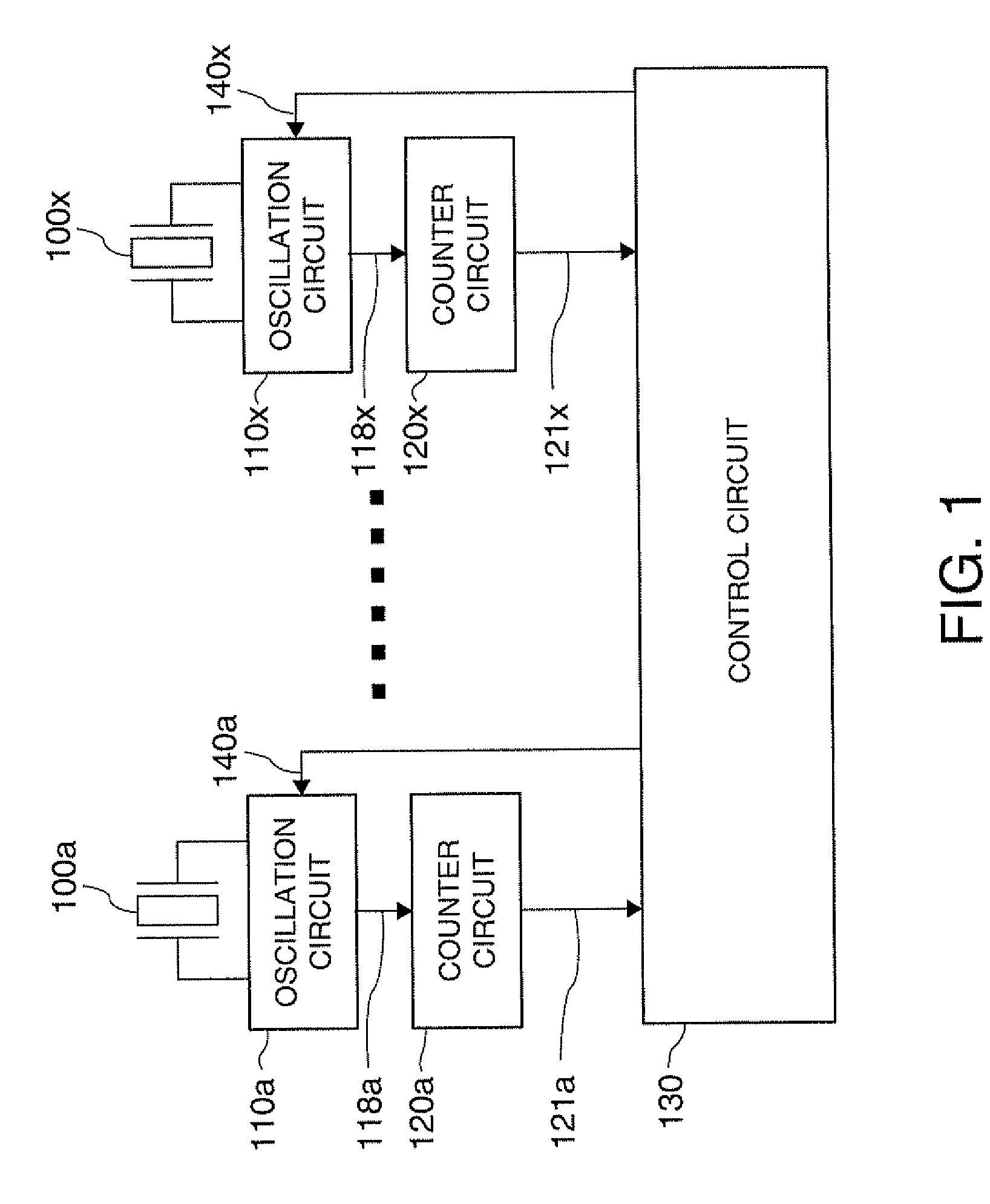
[0091]According to the frequency measuring device configured as described above, since a frequency difference between the oscillation signals 118a to 118x output from the oscillation circuits 110a to 110x, respectively, are made greater than a predetermined frequency difference, it is possible to prevent the drawing effect from occurring between the oscillation circuits 110a to 110x. This eventually makes it possible to prevent the drawing effect from causing a problem in the operation of the frequency measuring device.

[0092]Moreover, when the control circuit 130 performs a series of processes by rearranging the frequencies fa to fn in descending order of frequency (S220), the control circuit 130 performs a process to decrease the frequency when regulating the frequencies of the oscillation signals 118a to 118x. By doing so, it is possible to regulate the frequencies of the oscillation signals 118a to 118x without increasing the power consumption of th...

second embodiment

(2) Feature of Second Embodiment

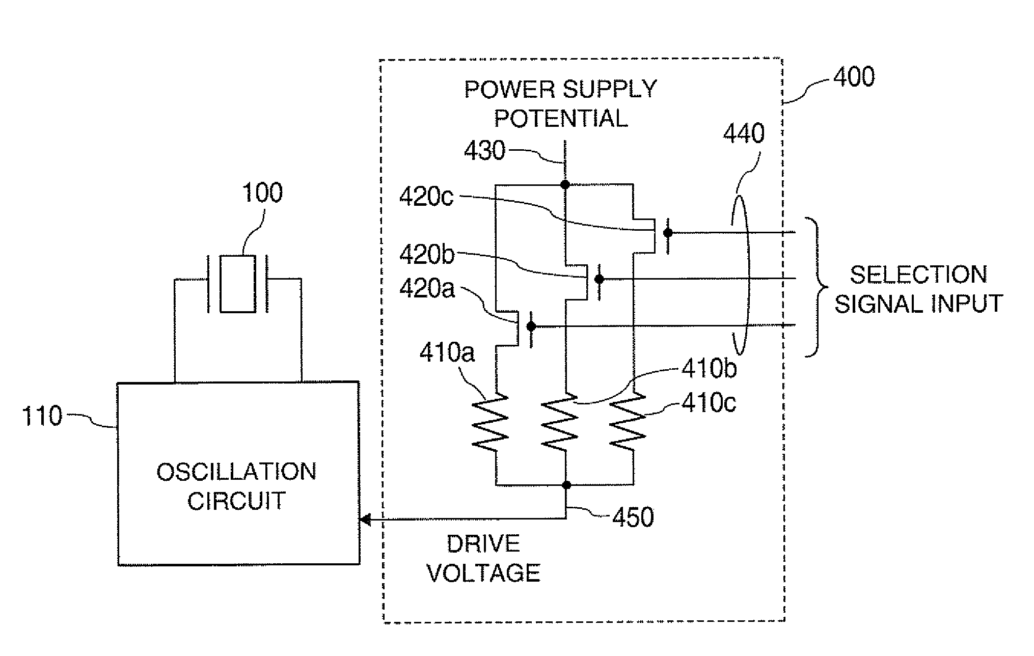
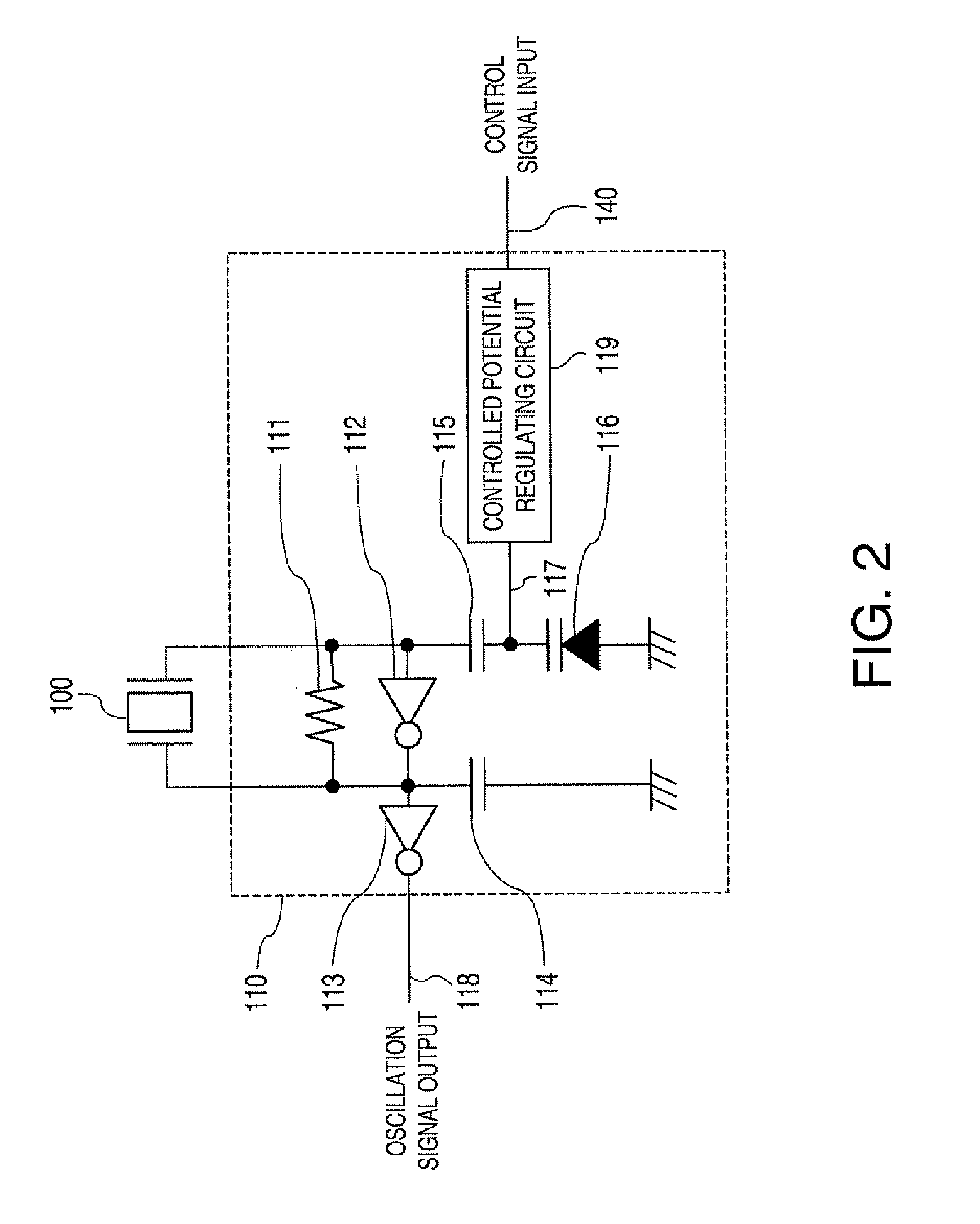
[0106]According to the frequency measuring device configured as described above, the drive voltage generating circuit 400 as the frequency regulator is provided. This makes it possible to provide a frequency measuring device which can regulate the frequencies of the oscillation signals 118 only by changing the drive voltage while allowing the plurality of oscillation circuits 110 of the frequency measuring device to have a commonly-used configuration.

[0107]Moreover, as in the second embodiment, by providing the serial-parallel converter 460, it is possible to control the plurality of switching elements 420a to 420c included in the drive voltage generating circuit 400 by a 1-bit control signal 140. This makes it possible to reduce the number of signal lines used and facilitate connection between the control circuit 130 and the oscillation circuit 110, for example.

4. THIRD EMBODIMENT

[0108]Next, a third embodiment of the invention will be described with ...

third embodiment

(2) Feature of Third Embodiment

[0116]According to the operation of the third embodiment, it is possible to control the frequency regulators so that the frequency difference between the oscillation signals 118a to 118x becomes greater than the predetermined frequency difference in a shorter time compared to the operation of the first embodiment.


PUM

PropertyMeasurementUnit
frequencyaaaaaaaaaa
frequencyaaaaaaaaaa
frequency measuringaaaaaaaaaa

Abstract

A frequency measuring device according to an embodiment of the invention includes a first resonator provided with a first adsorption film, a second resonator provided with a second adsorption film, a first oscillation circuit which is connected to the first resonator and is provided with a first frequency regulator that can regulate the frequency of a first oscillation signal and output the first oscillation signal, a second oscillation circuit which is connected to the second resonator and is provided with a second frequency regulator that can regulate the frequency of a second oscillation signal and output the second oscillation signal, a measuring circuit which can measure the frequencies of the first oscillation signal and the second oscillation signal, and a control circuit which can control the first frequency regulator and the second frequency regulator.

Description

[0001]The entire disclosure of Japanese Patent Application No. 2010-137267, filed Jun. 16, 2010 is expressly incorporated by reference herein.BACKGROUND[0002]1. Technical Field[0003]An embodiment of the present invention relates to a frequency measuring device etc. provided with a plurality of sets of a resonator having an adsorption film and an oscillation circuit connected to the resonator.[0004]2. Related Art[0005]A phenomenon occurs in which, when a substance contained in a surrounding medium is attached to the surface of a quartz crystal resonator under a resonant condition, the resonance frequency changes according to the attached substance. A technique using this phenomenon is called QCM (quartz crystal microbalance) and used as a sensor detecting the presence and the amount of molecules contained in the surrounding medium. As the application of QCM, there is an odor sensor having a resonator with a surface on which an adsorption film which selectively adsorbs a particular mo...

Claims


Application Information

Patent Timeline
Patent Type & Authority Patents(United States)
IPC IPC(8): G01N29/02G01R23/00
CPCG01N29/022
Inventor KONDO, TAKAYUKITODOROKIHARA, MASAYOSHI
Owner SEIKO EPSON CORP
Why Eureka
Try Eureka