
Optical transmission module and its temperature adjustment method

a technology of optical transmission module and temperature adjustment method, which is applied in the direction of optical elements, instruments, gas-filled discharge tubes, etc., can solve the problems of large c, and deterioration of the characteristics of the ld at high temperatures, so as to prevent the deterioration of the characteristics of the light source element, the effect of stably operating and saving power

Active Publication Date: 2014-12-23
CLOUD LIGHT TECH LTD
View PDF3 Cites 0 Cited by
  • Summary
  • Abstract
  • Description
  • Claims
  • Application Information

AI Technical Summary

Benefits of technology

The present invention provides an optical transmission module that can stably operate in a wide temperature range while saving power and reducing cost. By connecting the driver circuit to the light source element through a heat transfer member, heat generated at the driver circuit can be transferred to the light source element to increase its temperature, preventing the light source element from operating at a low temperature. The module also includes a switch unit that can automatically adjust the temperature of the light source element by switching between contact and separation of two members, further preventing deterioration of the light source element's characteristics. Overall, this patent provides an optical transmission module that can maintain optimal performance and stability while reducing energy consumption.

Problems solved by technology

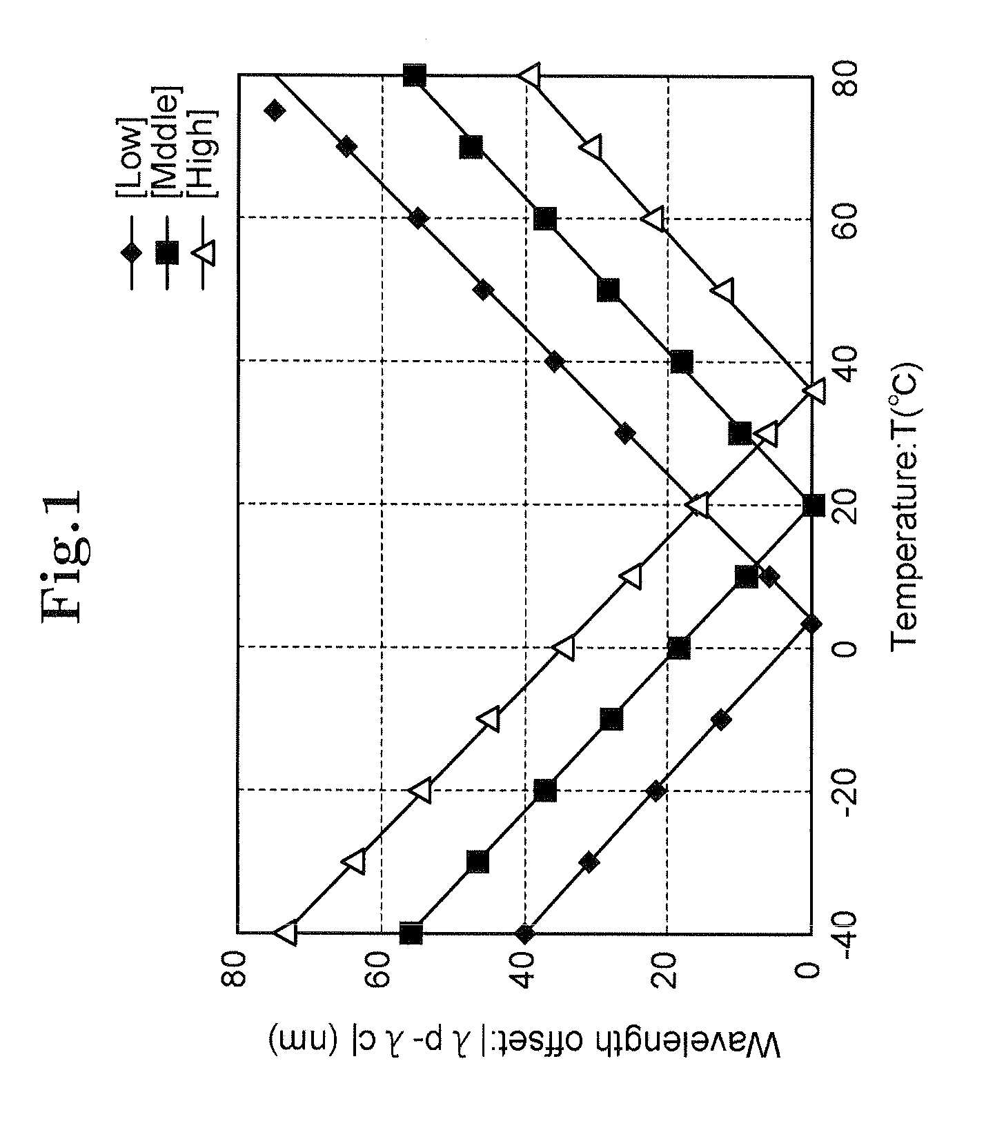
Accordingly, when the resonator or the reflecting mirror is designed so that the characteristics of the semiconductor laser become optimum, that is, λp matches λc at high temperatures, the difference between λp and λc becomes large at low temperatures, thereby deteriorating the characteristics of the LD.
Conversely, when the resonator or the reflecting mirror is designed so that the characteristics of the semiconductor laser become optimum at low temperatures, the characteristics of the LD deteriorate at high temperatures.
In other words, disadvantageously, it is difficult to provide an optical transmission module, unlike the optical transmission module described in Patent document 1, which stably operates in a wide temperature range at low costs without consuming excessive electric power.

Method used


Image

  • Optical transmission module and its temperature adjustment method
  • Optical transmission module and its temperature adjustment method
  • Optical transmission module and its temperature adjustment method

Examples


first embodiment

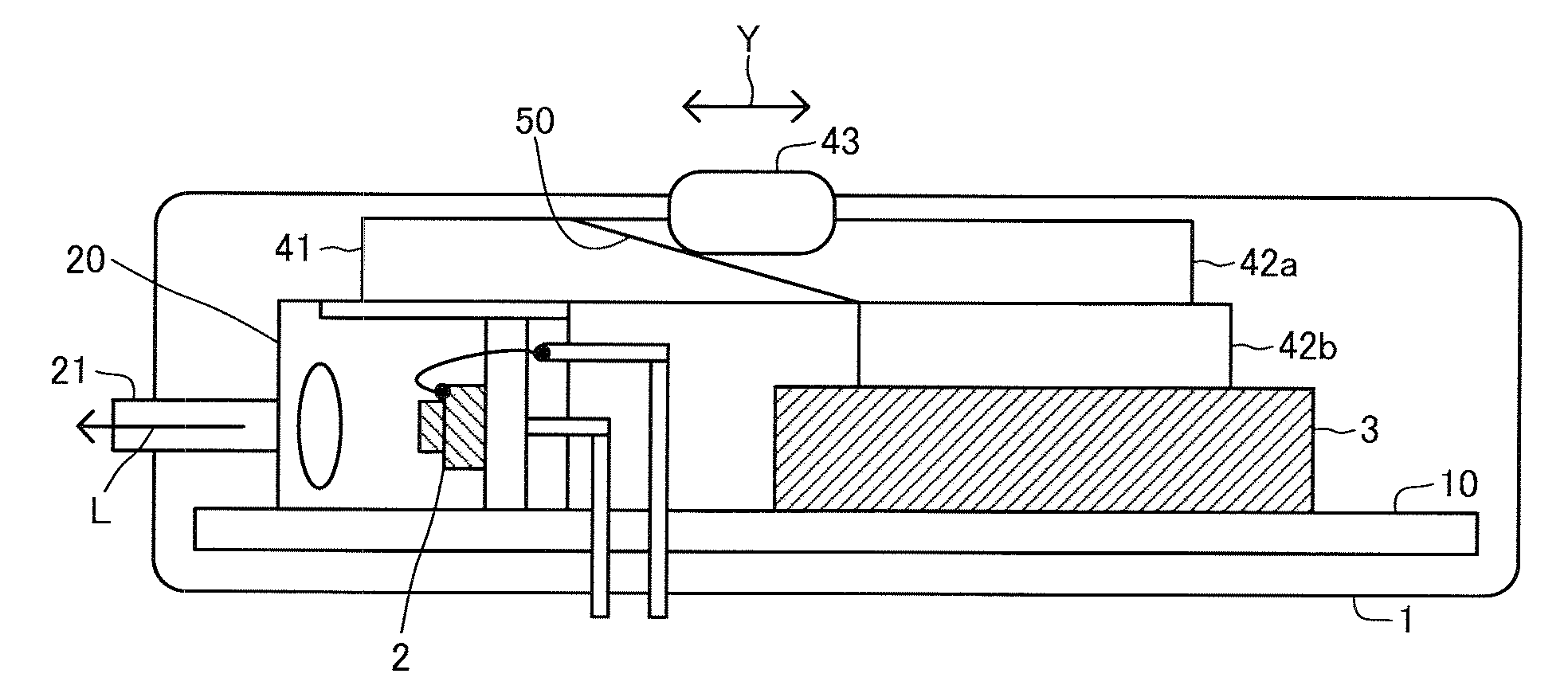
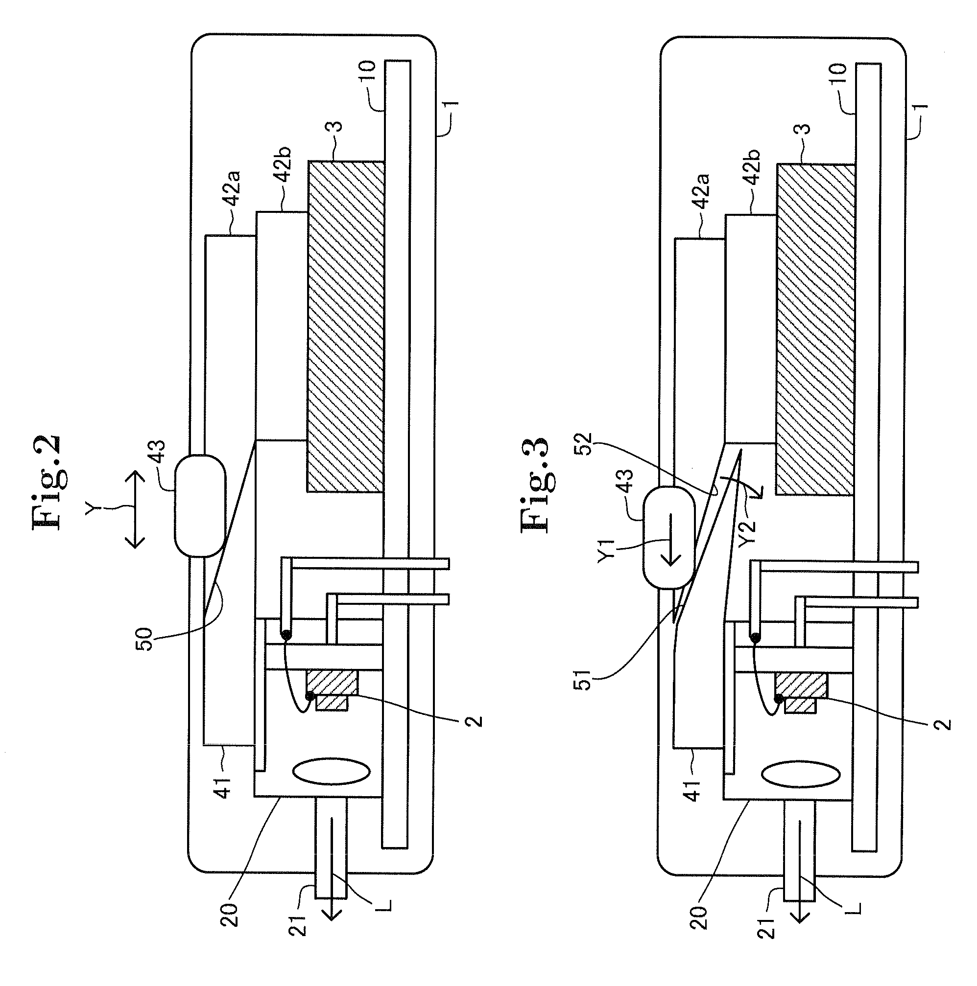
[0037]First embodiment of the present invention will be described with reference to FIG. 1 to FIG. 5. FIG. 1 is a view for describing characteristics of a light source element mounted in an optical transmission module. FIG. 2 to FIG. 4 are views showing configuration of the optical transmission module. FIG. 5 is a flowchart showing operations of the optical transmission module.

[0038]The optical transmission module 1 of the present invention is an optical transmission module for optical interconnection and includes a semiconductor laser 2 as a light source element. The semiconductor laser in this embodiment is, in particular, a VCSEL. However, the semiconductor laser 2 is not limited to the VCSEL and may be another semiconductor laser such as a DBR laser or a DFB laser. Further, the light source element is not limited to the semiconductor laser.

[0039]In the VCSEL as the semiconductor laser 2 in this embodiment, a wavelength (λc) of an emitted laser beam is determined by a resonator o...


PUM


Abstract

An optical transmission module includes a light source element for emitting a predetermined light signal transmitted through an optical fiber, the light source element having lower characteristics in a low-temperature state than those in a high-temperature state, a driver circuit for driving the light source element, and a heat transfer member connected to each of the light source element and the driver circuit to transfer heat between the light source element and the driver circuit. The optical transmission module with such configuration can stably operate in a wide temperature range while achieving power saving and cost reduction.

Description

[0001]This application claims priority to Japanese Application No. 2010-272227 filed 7 Dec. 2010, the entire contents of which is hereby incorporated by reference.TECHNICAL FIELD[0002]The present invention relates to an optical transmission module, in particular, to an optical transmission module having a temperature adjustment function. The present invention also relates to a temperature adjustment method of the optical transmission module.BACKGROUND ART[0003]In an optical transmission module for optical interconnection, a light source element is required to operate in a wide temperature range from −40° C. to 80° C., for example. In order to meet such requirement, Patent document 1 discloses an optical transmission module provided with a temperature adjustment member such as a Peltier device or a heater so as to maintain a laser diode at a constant temperature.[0004]However, since the above-mentioned optical transmission module is provided with the Peltier device or the heater, it ...

Claims


Application Information

Patent Timeline
Patent Type & Authority Patents(United States)
IPC IPC(8): H01J19/74H01J7/24G02B6/36H01J61/52H01J13/32G02B6/42H01S3/04H01J17/28G02B7/02
CPCG02B6/4266
Inventor TAMANUKI, TAKEMASA
Owner CLOUD LIGHT TECH LTD
Learn More