Transport unit

a technology of transport unit and telescopic carriage, which is applied in the direction of programmed manipulators, pile separation, lifting devices, etc., can solve the problems of complicated telescopic carriage arrangement and limited kinematics of this press transfer system, and achieve the effect of reducing opening width requirements, low overall height, and fast and accurate movement of the gripping tool and the held workpi

Active Publication Date: 2014-12-23
KUKA SYSTEMS
View PDF19 Cites 7 Cited by
  • Summary
  • Abstract
  • Description
  • Claims
  • Application Information

AI Technical Summary

Benefits of technology

[0005]Therefore, an object of the present invention is to provide an improved transport technique for workpieces.
[0006]The transport technique according to the invention has the advantage of high movability and flexibility. The transport unit may have, e.g., eight or more axes, which may be separately controllable. Consequently, it is possible to achieve a highly flexible kinematics and an adaptation to different machining devices and their set up conditions, especially at presses in a press working line. The transport unit can be used for the widest variety of machining devices. It may be adapted in a simple manner to varying distances between adjacent machining devices as well. A reprogramming of the robot is sufficient for this in most cases.
[0007]The highly flexible transport unit can raise and lower the workpieces and can also transport them to any and especially a largely straight track between the machining devices. This fast and efficient kinematics is favorable for achieving a high transport speed and a correspondingly fast machining cycle, especially press cycle. The transport unit may otherwise also reorient (possibly transport to a curved track) the workpieces as needed.

Problems solved by technology

The kinematics of this press transfer system is limited and brings about the complicated telescopic carriage arrangement.

Method used


Image

  • Transport unit
  • Transport unit
  • Transport unit

Examples


first embodiment

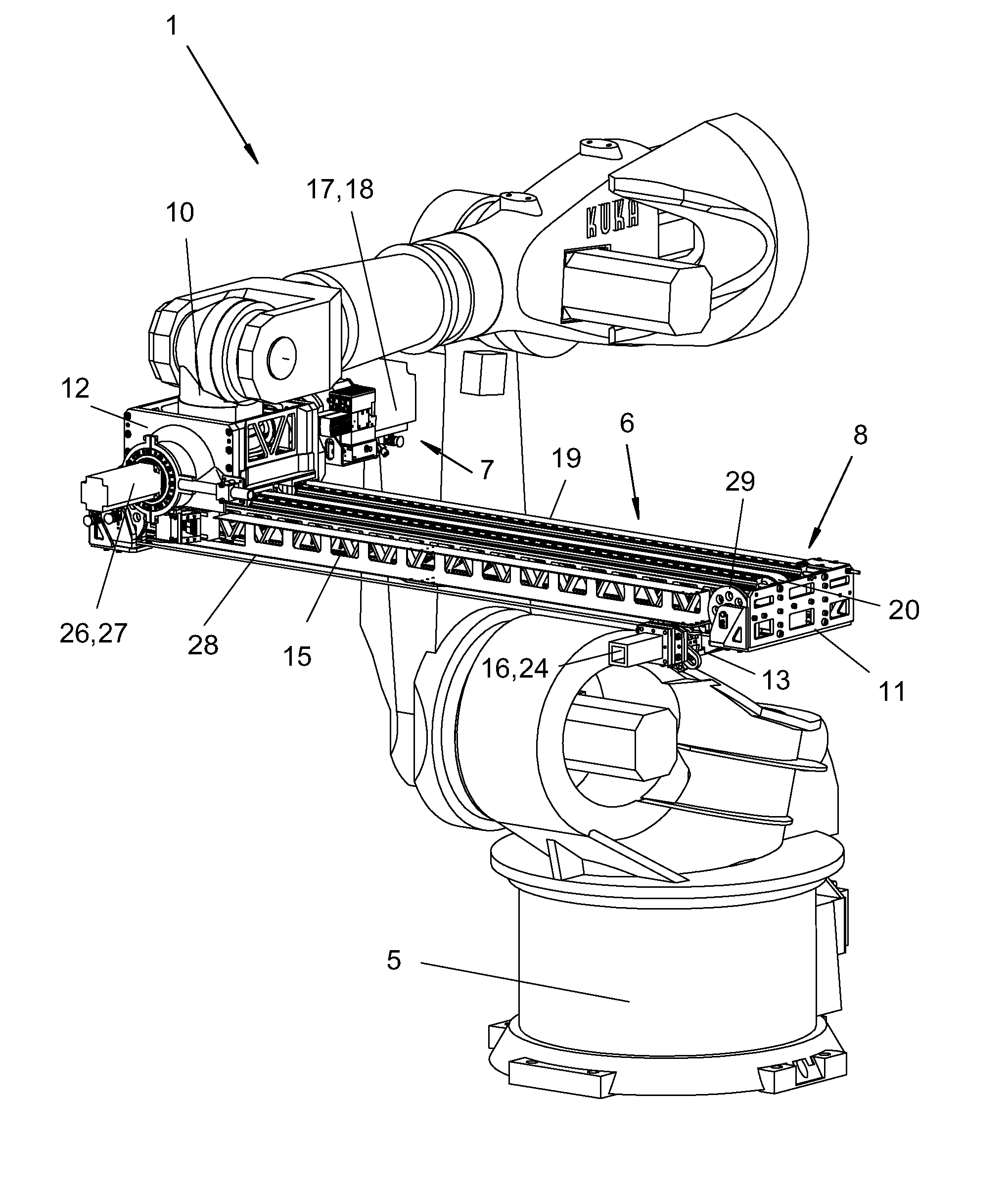
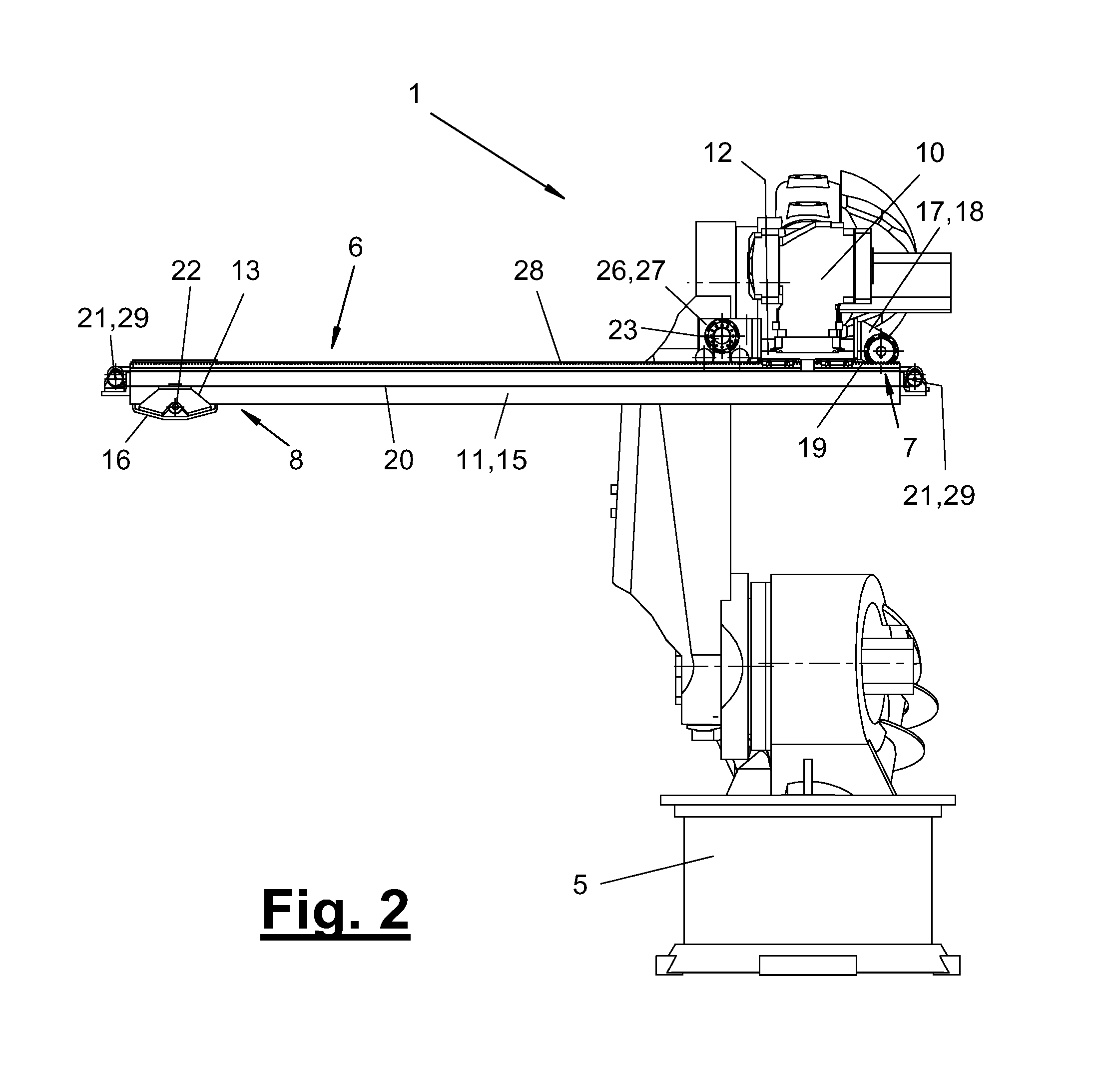
[0056]In FIG. 2, the transmission means (19) is designed as a rack-and-pinion drive, whereby motor (18) drives a pinion directly or via an upstream gear, which pinion meshes with a rack aligned along the support bar (11) and arranged on the top side of same. The second variant of FIG. 3 may also have such a rack-and-pinion drive or a different drive, which converts the motor rotation into a translatory movement of the support bar (11).

third embodiment

[0057]In FIGS. 4 through 10, the transmission means (19) is designed as a belt drive, whereby a pinion associated with the motor (18) meshes with a toothed belt in an omega loop that is finite and fixed with both ends at the front areas of the support bar (11). The belt drive (19) is arranged, e.g., on the top side and at a longitudinal edge of the support bar (11).

[0058]There are likewise various embodiments for the pivot drive (26). It is used to influence the rotary or pivoting position of the tool holder (16) at its carriage (13), whereby this is uniformly possible in all carriage positions.

[0059]The pivot drive (26) may likewise have a controllable motor (27). As in the feed drive (17), this may be an electric motor, especially an electric servomotor, which is likewise connected to the robot control system and makes possible a fast and exact workpiece rotation and a positioning and holding of the rotary position as well. The holding forces can be applied by the motors (18, 27) ...


PUM


Abstract

A transport unit (1) is provided for workpieces (2), in particular sheet metal parts, between neighboring placement areas or machining devices (3, 4), in particular presses. The transport unit (1) includes a multi-axis robot (5) having a gripper tool (9). A controllable transfer unit (6) is also provided that is guided by the robot (5). The unit includes an advancement unit (7) and a pivot unit (8) for the gripper tool (9).

Description

CROSS REFERENCE TO RELATED APPLICATIONS[0001]This application is a United States National Phase application of International Application PCT / EP2010 / 068555 and claims the benefit of priority under 35 U.S.C. §119 of German Utility Model DE 20 2009 015 682.6 filed Dec. 1, 2009, the entire contents of which are incorporated herein by reference.FIELD OF THE INVENTION[0002]The present invention pertains to a transport unit for workpieces, especially sheet-metal parts, between adjacent deposit sites or machining devices, especially presses, wherein the transport unit has a multiaxle robot with a gripping tool.BACKGROUND OF THE INVENTION[0003]Such a transport unit for sheet-metal parts is known from DE 202 16 013 U1. It is designed as a press transfer system, with which sheet-metal parts are transported between adjacent sheet-metal presses of a press working line. The transport unit has a multiaxle robot with a gripping tool. The gripping tool is arranged at the end at an extension arm flan...

Claims


Application Information

Patent Timeline
Patent Type & Authority Patents(United States)
IPC IPC(8): B25J9/04B21D43/05B25J18/02B21D43/10G06F7/00
CPCB21D43/05B21D43/105B25J9/047B25J18/02
Inventor CHO, YONG-HAKHOLECEK, THOMASGASTL, MATTHIASMOCKER, SEBASTIANHENNEKE, THOMAS
Owner KUKA SYSTEMS
Why Eureka
Try Eureka