Battery module with high thermal conductivity and assembling method thereof

a battery module and high thermal conductivity technology, applied in the manufacture of cell components, final product details, cell components, etc., can solve the problems of affecting the life of battery cells, affecting the safety of electric vehicles, and requiring a lot of battery cells for battery packs, so as to prevent accidental cell damage or short circuit, increase the safety of battery packs during operation, and improve the effect of thermal conduction path

Active Publication Date: 2014-12-30
ATIEVA USA INC
View PDF15 Cites 68 Cited by
  • Summary
  • Abstract
  • Description
  • Claims
  • Application Information

AI Technical Summary

Benefits of technology

[0024]In the battery module disclosed herein, the battery cells are enclosed within the accommodation chambers and electrically connected to the top and bottom common electrodes. The retaining holes and accommodation holes are formed with one or more interference flanges for holding the battery cells within the accommodation chambers. A heatsink device is coupled to the primary retaining frame and / or the secondary retaining frame. Advantageously, the heatsink device abuts against the top common electrode and / or the bottom common electrode of the battery cells. By virtue of the arrangement disclosed herein, the electrical connection among the battery cells will not be adversely affected by severe shock or vibration, thereby preventing the occurrence of accidental cell damage or short circuit and increasing battery pack safety during operation. The tight interference fit also assures good thermal conduction path from battery cells to heatsink even at severe shock and vibration conditions.
[0025]During maintenance, the technicians can simply replace the battery modules which contain damaged or low capacity battery cells with functional battery modules. Manpower needed for maintenance works is thus reduced considerably. The invention achieves the objects described above accordingly.

Problems solved by technology

Higher energy density cells require more chemically active materials and inherently less stable and more difficult to design battery systems with high safety margins.
However, battery pack for electric vehicles requires a lot of battery cells.
Without careful thermal design, battery cell temperature could elevate up to 30 Celsius above ambient, with detrimental effect on battery cell life.
Battery system for vehicle operation is often 5 years or more, thermal management is a tough design issue for vehicle applications.
Furthermore, high energy density battery cells become unstable when internal temperature exceeds 80 degree Celsius.
It is cell chemistry and process dependent, and the probability of thermal run away, cell venting, and fire and explosion increases dramatically beyond such safe temperature limit.
When one battery cell goes into thermal runaway, either through violation of safe temperature limit, manufacturing process induced cell short circuit, over charge, or external impact from vehicle crashes, the amount of energy released may cause adjacent battery cells to also go into thermal runaway, this chain reaction destroys the battery pack and place the vehicle passengers in great physical danger.
Unfortunately, cooling is often compromised in a vehicle crash, and damaged battery cells could spark thermal runaway that leads to explosion and vehicle fire.
It is hindered by the poor thermal conductivity of the cell sidewall and not effective in heat removal.
Every 10 degrees Celsius higher cell temperature halves the battery operating life, prior art battery pack design often cannot meet operating life requirement without stipulating a cooler air inlet temperature than ambient temperature.
Under high shock and vibration vehicle operation, thermal connection from the top / bottom surface of battery cells to external heat sinks can be broken.
If battery cell to mechanical housing design is not robust, cell wall can rub against housing under high shock and vibration vehicle operation and sustain damages.
Physically damaged cell will lead to shorter operation life.
Physically damaged cells can leak flammable electrolyte into the battery pack, creating a fire hazard.
Physically damaged cell can also lead to thermal runaway.

Method used


Image

  • Battery module with high thermal conductivity and assembling method thereof
  • Battery module with high thermal conductivity and assembling method thereof
  • Battery module with high thermal conductivity and assembling method thereof

Examples


Embodiment Construction

[0036]The following description is provided to enable any person having ordinary skill in the art to make and use the invention, and is provided in the context of a particular application and its requirements. Various modifications to the embodiments will be readily apparent to those skilled in the art, and the principles defined herein may be applied to other embodiments and applications without departing from the spirit and scope of the invention. Thus, the present invention is not intended to be limited to the embodiments shown, but is to be accorded the widest scope consistent with the principles, features and teachings disclosed herein.

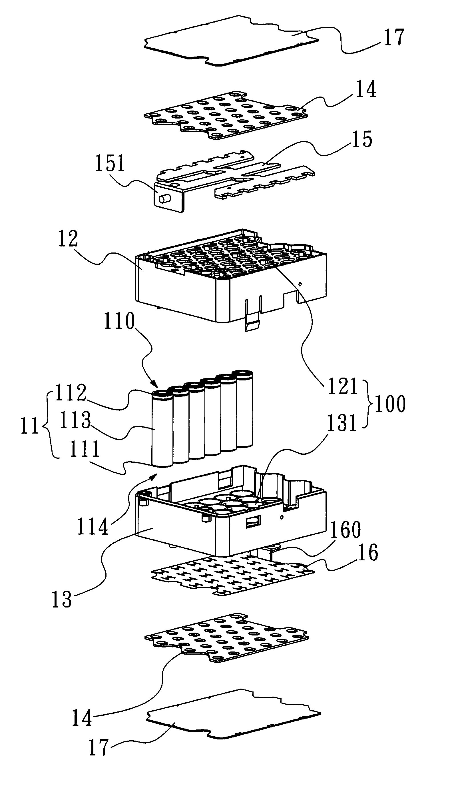
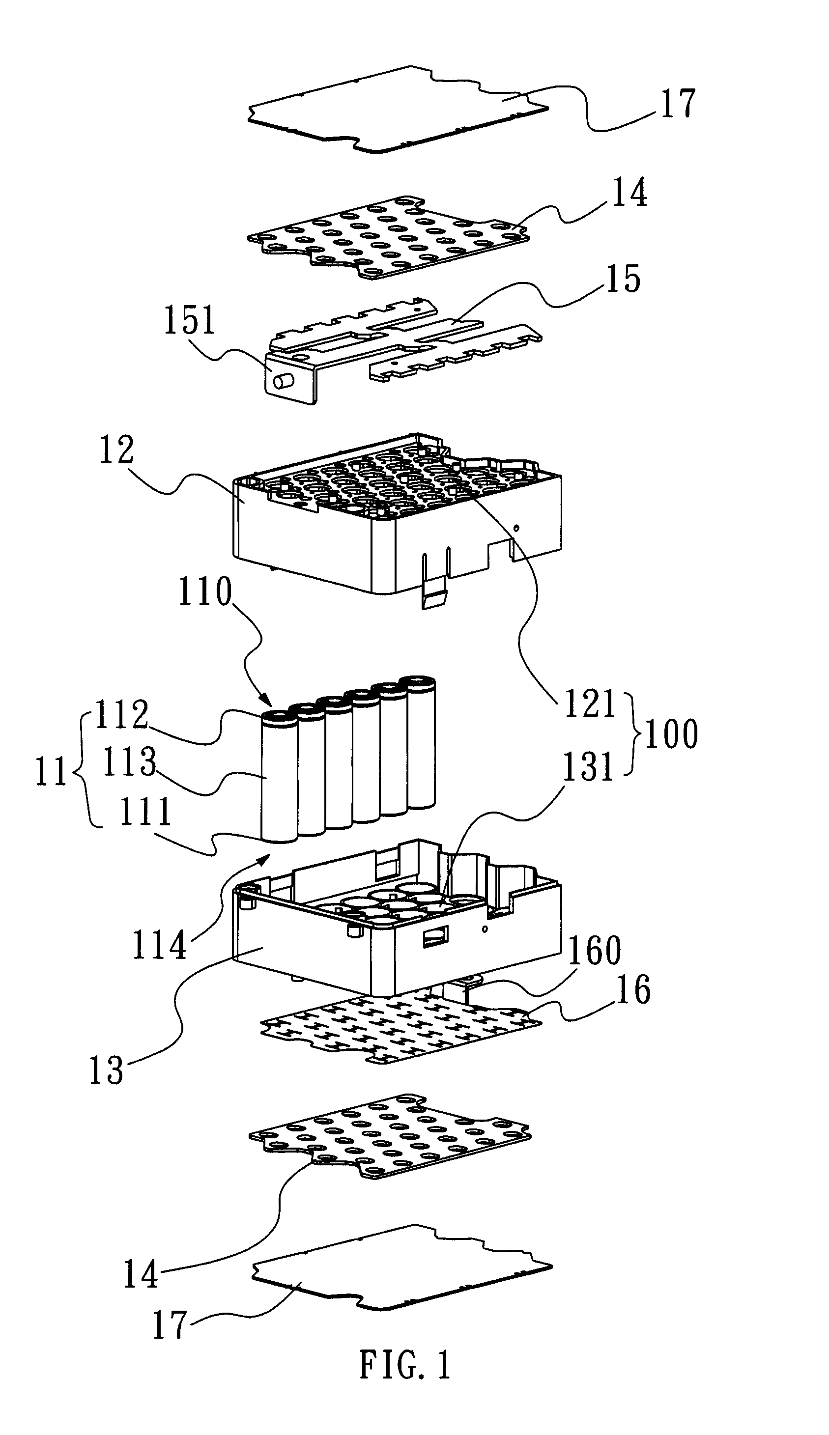
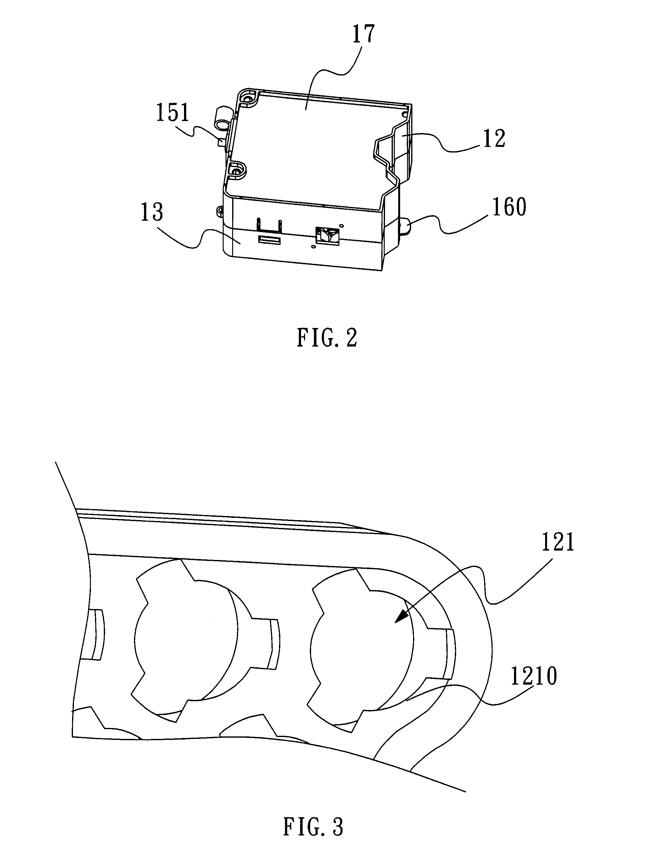
[0037]FIG. 1 and FIG. 2 show the battery module with high thermal conductivity according to the first preferred embodiment of the invention, which includes multiple battery cells 11, a primary retaining frame 12, a secondary retaining frame 13, a common electrode and a heatsink device. The common electrode is divided into a top common electrode 1...


PUM

PropertyMeasurementUnit
temperatureaaaaaaaaaa
thermal conductivityaaaaaaaaaa

Abstract

A battery module with high thermal conductivity and its assembling method are disclosed. The battery module includes multiple battery cells, a primary retaining frame, a secondary retaining frame, common electrodes and a heatsink device. The primary and second retaining frames are combined together to constitute accommodation chambers for housing the battery cells and formed with interference flanged to secure the battery cells in position. Upon being inserted into the accommodation chambers, the battery cells are electrically connected to the common electrodes. The heatsink device is then coupled to the primary retaining frame and/or the secondary retaining frame, such that the heatsink device abuts against the top common electrode and/or the bottom common electrode of the battery cells.

Description

FIELD OF THE INVENTION[0001]The present invention relates to a battery module with high thermal conductivity and an assembling method thereof and, more particular, to a battery assembly structure in which multiple battery cells are arranged in a mechanically robust housing with high thermal conduction characteristics, and an assembling method thereof.BACKGROUND OF THE INVENTION[0002]The invention of high energy density battery technologies initiated the market of cellular phones, notebook computers, electric cars, and grid storage applications. The market demand for smaller form factor and longer operating hours pushing the battery makers to invent higher and higher energy density battery cells. Higher energy density cells require more chemically active materials and inherently less stable and more difficult to design battery systems with high safety margins.[0003]Most high energy density battery cells are consumed in cellular phones and portable computers. Total energy required for...

Claims


Application Information

Patent Timeline
Patent Type & Authority Patents(United States)
IPC IPC(8): H01M2/20H01M2/10H01M50/213H01M50/227H01M50/276H01M50/502
CPCH01M2/10H01M10/04H01M2/1083H01M2/202H01M2/1077H01M10/613H01M10/653H01M10/6554Y02E60/10H01M50/502Y02P70/50H01M50/276H01M50/227H01M50/213
Inventor CHUANG, CHARLES CHIA-MINGTSAI, BENSON
Owner ATIEVA USA INC
Why Eureka
Try Eureka