FMCW radar sensor for motor vehicles

a technology for fmcw radar and motor vehicles, applied in the direction of linear waveguide fed arrays, instruments, and using reradiation, can solve problems such as problematic automatic blindness recognition, and achieve the effect of simple and reliable blindness recognition, improved object positioning and characterization

Inactive Publication Date: 2014-12-30
ROBERT BOSCH GMBH
View PDF33 Cites 7 Cited by
  • Summary
  • Abstract
  • Description
  • Claims
  • Application Information

AI Technical Summary

Benefits of technology

[0009]An object of the present invention is to create an FMCW radar sensor for motor vehicles, which allows a more reliable location of objects in front of the vehicle, in particular of preceding vehicles.
[0012]The construction of the antenna elements from multiple serially fed subelements has the result that the frequency modulation within the particular frequency band also results in a specific variation of the emission characteristic in the vertical. Since this modulation occurs periodically having a relatively short cycle time, however, it only results in “wobbling” of the radar beam in the vertical, which does not impair the function of the radar sensor as a whole and is even advantageous, because it results in a certain expansion of the locating range in the vertical. For the duration of multiple successive measuring cycles, which are required for reliably locating an object, the frequency position of the frequency band remains virtually constant, so that the evaluation of the received signal is not made more difficult.
[0013]In practical use of the radar sensor in the motor vehicle, the possibility of varying the directional characteristic in the elevation offers several noteworthy advantages. For example, maladjustments of the radar sensor in the elevation may be corrected simply by adapting the frequency band, without the installation of the radar sensor having to be changed.
[0015]Furthermore, when traveling on a level roadway, the locating of the objects and their characterization may also be improved by changing the elevation. For example, the elevation may be optimized in each case by a suitable algorithm in such a way that particularly strong radar echoes are obtained. It is optionally also possible to differentiate between taller and flatter objects by varying the elevation while following a located object, so that the objects may be better characterized, for example, as trucks, passenger automobiles, guard rails on the roadway edge, or completely irrelevant objects such as manhole covers or tin cans on the roadway surface.
[0016]If a radar sensor in a driver assistance system of a motor vehicle is used, for example, for automatic adaptive cruise control or in a so-called precrash system for collision warning, for collision avoidance, or for preparing passive safety systems for an imminent collision, an important safety requirement is that one may be sure at all times that the radar sensor is actually functional and is not blinded because of a snow or ice covering on the radar lens, for example. An automatic blindness recognition has been problematic up to this point above all, however, because even in the case of a blinded radar sensor, reflections, which may be incorrectly interpreted as located object, indeed occur. In the case of a real object, however, it is to be expected that the radar echo changes in some form if the emission characteristic is changed in elevation. The reflections which occur on a blinded radar sensor are however independent of the elevation. The present invention thus also allows particularly simple and reliable blindness recognition.

Problems solved by technology

An automatic blindness recognition has been problematic up to this point above all, however, because even in the case of a blinded radar sensor, reflections, which may be incorrectly interpreted as located object, indeed occur.

Method used


Image

  • FMCW radar sensor for motor vehicles
  • FMCW radar sensor for motor vehicles
  • FMCW radar sensor for motor vehicles

Examples


Embodiment Construction

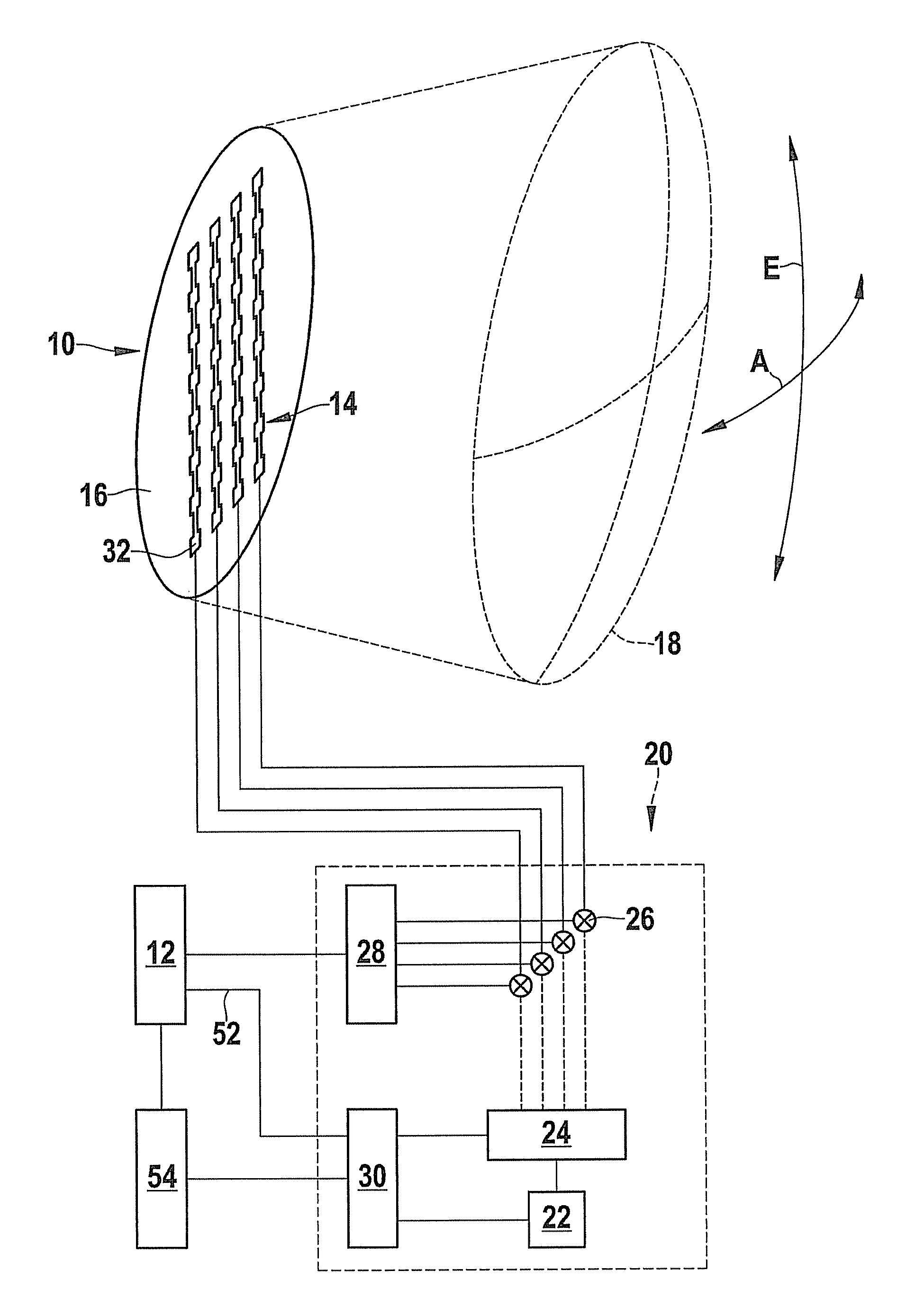
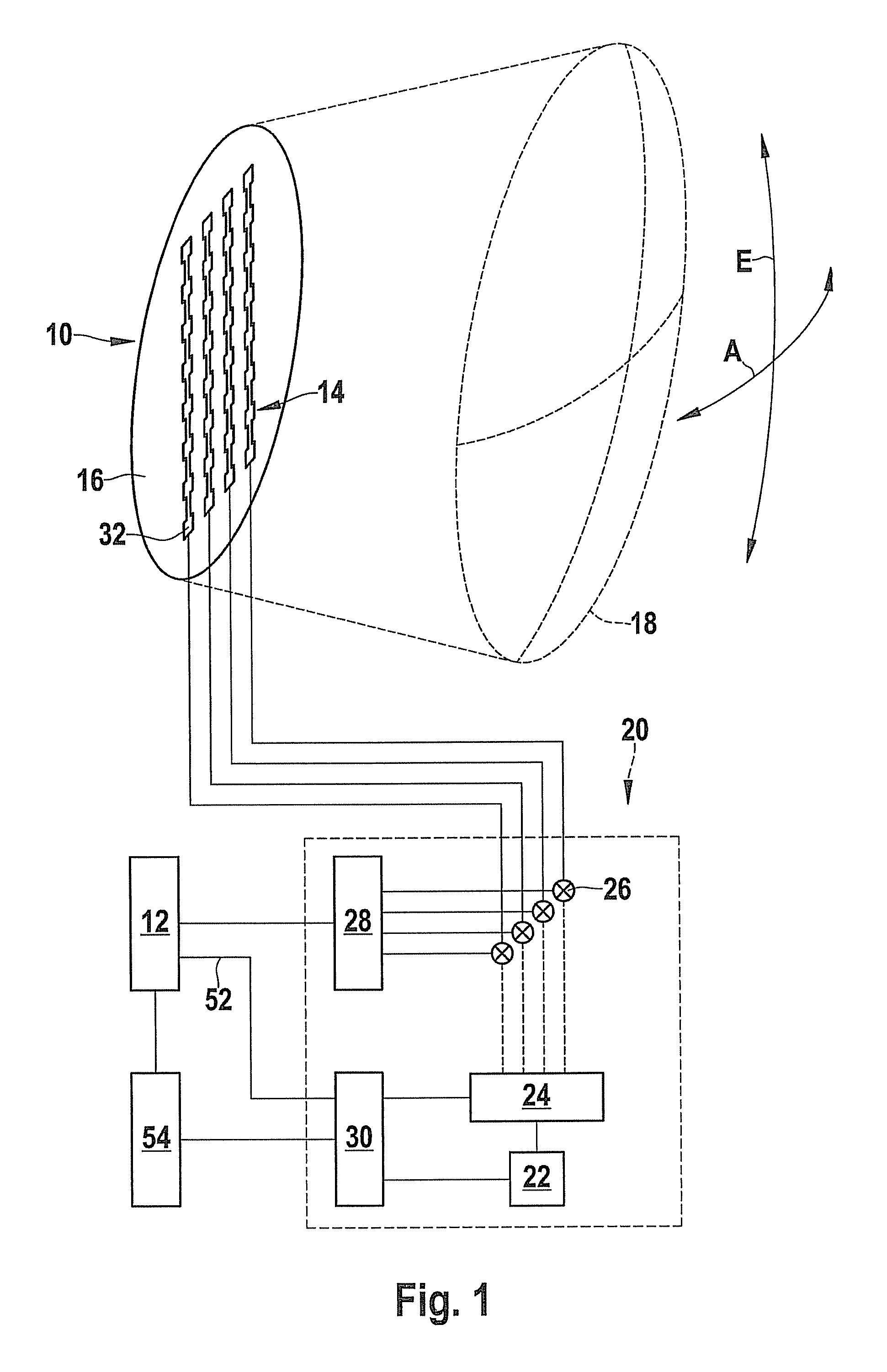
[0022]FIG. 1 shows, in a simplified block diagram, the main components of a driver assistance system for motor vehicles, for example, an adaptive cruise control (ACC), having a radar sensor 10 installed in the vehicle and an evaluation device 12 in the form of an electronic data processing system. Radar sensor 10 is used to locate preceding vehicles, and evaluation device 12 interferes, on the basis of the locating data of the radar sensor, in the drive and braking systems of the vehicle, in order to regulate the velocity of the vehicle in such a way that a vehicle, which is directly preceding in the same lane, is followed at an appropriate safety distance.

[0023]Radar sensor 10 has a circuit board 16, which is equipped with antenna elements 14 (four in the example shown), and which is positioned at a distance to a microwave lens 18. A drive circuit 20, which is shown as a block in FIG. 1, is positioned at or on circuit board 16, having a voltage-controlled oscillator 22, a phase-loc...


PUM


Abstract

FMCW radar sensor for motor vehicles, having at least one antenna element and a modulation device for feeding the antenna element using a frequency-modulated transmission signal, whose frequency periodically sweeps a frequency band, characterized in that the antenna element has multiple subelements, which are positioned in a vertical column and fed serially, and the modulation device is implemented for the purpose of variably setting the frequency position of the frequency band.

Description

RELATED APPLICATION INFORMATION[0001]The present application is a U.S. national phase patent application of PCT application PCT / EP2009 / 063730, which was filed on Oct. 20, 2009, and which claims priority to and the benefit of German patent application no. DE 102008054624.0, which was filed in Germany on Dec. 15, 2008, the disclosures of which are incorporated herein by reference.FIELD OF THE INVENTION[0002]The present invention relates to an FMCW radar sensor for motor vehicles, having at least one antenna element and one modulation device for feeding the antenna element with a frequency-modulated transmission signal, whose frequency periodically sweeps a frequency band.BACKGROUND INFORMATION[0003]In conventional FMCW radar sensors (frequency modulated continuous wave), the frequency is modulated in the form of a ramp within a fixed frequency band, for example alternately using a rising frequency ramp and a falling frequency ramp.[0004]The received radar echo is mixed with a componen...

Claims


Application Information

Patent Timeline
Patent Type & Authority Patents(United States)
IPC IPC(8): H01Q3/22G01S13/93G01S7/28G01S7/40H01Q1/32G01S13/34H01Q21/00G01S13/931
CPCG01S7/4004G01S2007/4039G01S2013/9325H01Q3/22H01Q1/3233G01S13/931H01Q21/0037G01S13/345G01S2013/9321G01S7/4039G01S13/426
Inventor KLAR, MICHAELBINZER, THOMASHEILMANN, STEFAN
Owner ROBERT BOSCH GMBH
Why Eureka
Try Eureka