Radiation image detecting device and control method thereof, and radiation imaging system

a technology of radiation image and detection device, which is applied in the direction of material analysis using wave/particle radiation, instruments, applications, etc., can solve the problems of reducing the image quality of the roi, affecting the accuracy of the x-ray source, and the automatic setting process of the measurement field, so as to reduce the unnecessary radiation exposure of the patient, reduce the time for setting, and reduce the effect of unnecessary radiation exposur

Inactive Publication Date: 2014-12-30
FUJIFILM CORP
View PDF7 Cites 8 Cited by
  • Summary
  • Abstract
  • Description
  • Claims
  • Application Information

AI Technical Summary

Benefits of technology

[0022]According to the present invention, the measurement area setting circuit has the specified area mode and the automatic measurement area setting mode, and is arbitrary switchable therebetween. Thus, it is possible to use the optimal mode in accordance with an imaging situation including a patient's condition and the body part. The specified area mode eliminates the demerits of the automatic area setting mode, and contrarily, the automatic area setting mode eliminates the demerits of the specified area mode.
[0024]In the specified area mode, the measurement area is set up in a position predetermined in accordance with the body part to be imaged. Thus, the specified area mode needs less time for setting up the measurement area. Therefore, the X-ray emission time is more shortened in the specified area mode than in the automatic area setting mode. This reduces unnecessary radiation exposure of the patient, and prevents the occurrence of a blur in the radiation image due to a body motion. Also, since the measurement field is fixed in accordance with the body part, if there is any problem in the image quality of the radiation image, the problem could be solved easily only by checking the positioning between the measurement field and the body part to be imaged.
[0025]Also, the provision of the combination mode, which uses the specified area mode and the automatic area setting mode in conjunction with each other, facilitates optimal AEC performance in accordance with the actual imaging situation.

Problems solved by technology

Especially in oblique imaging in which the X-rays are applied to the patient in an oblique direction, since the measurement field is skewed with respect to the FPD, it is difficult to achieve precise positioning among the X-ray source, the FPD, and the ROI.
This causes excess or deficiency of an X-ray dose, and deteriorates the image quality of the ROI.
Also, an automatic setting process of the measurement field requires much time, as compared with a manual setting process by which the position of the measurement field is determined in accordance with the body part, and hence elongates X-ray emission time.

Method used


Image

  • Radiation image detecting device and control method thereof, and radiation imaging system
  • Radiation image detecting device and control method thereof, and radiation imaging system
  • Radiation image detecting device and control method thereof, and radiation imaging system

Examples


first embodiment

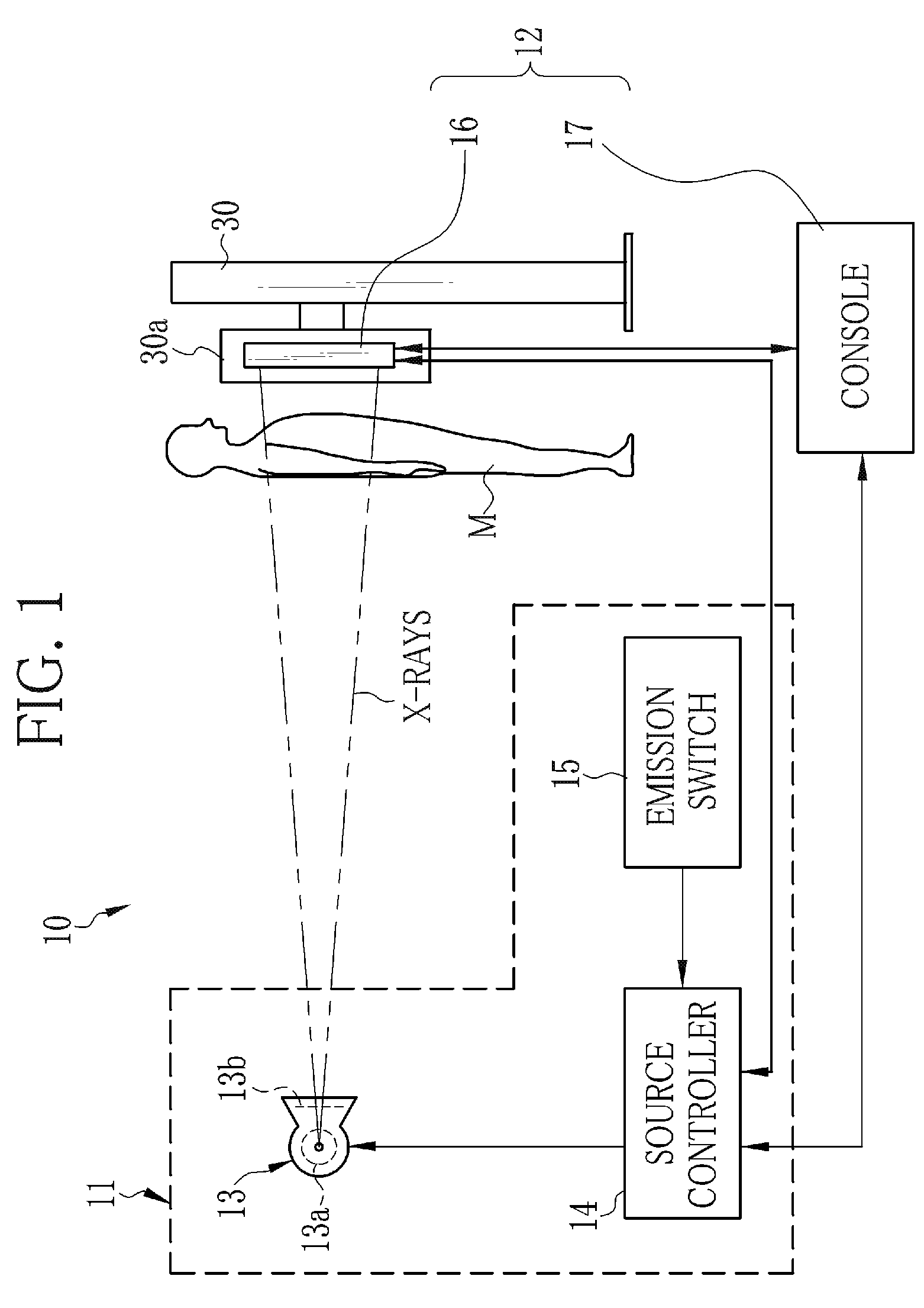
[0054]As shown in FIG. 1, an X-ray imaging system 10 is constituted of an X-ray generating device 11 for generating X-rays and an X-ray image detecting device 12 for producing an X-ray image from the X-rays passed through a body part being an object of a patient M. The X-ray generating device 11 includes an X-ray source 13 for emitting the X-rays, a source controller 14 for controlling the X-ray source 13, and an emission switch 15 for commanding the start of X-ray emission. The X-ray image detecting device 12 includes an electronic cassette 16 for detecting an X-ray image and a console 17 for controlling the electronic cassette 16. The source controller 14, the electronic cassette 16, and the console 17 are communicatably connected to each other through a wired or wireless communication unit.

[0055]The X-ray source 13 has an X-ray tube 13a for emitting the X-rays and a collimator 13b for limiting an irradiation field of the X-rays. The X-ray tube 13a has a cathode being a filament f...

second embodiment

[0117]In a second embodiment, the measurement area setting circuit 75 is switched between the specified area mode and the automatic area setting mode automatically in accordance with a body part to be imaged. An AEC section 120 shown in FIG. 11 is used instead of the AEC section 67 of the first embodiment. The AEC section 120 is provided with a mode switching circuit 121.

[0118]As shown in FIG. 12, the mode switching circuit 121 has a memory that stores combinations between a body part to be imaged and a mode to be selected. For example, a body part that requires relatively short X-ray emission time, such as chest, is combined with the specified area mode, because the automatic area setting mode takes long time to set up the measurement area. A body part that requires relatively long X-ray emission time, such as lumber vertebrae, is combined with the automatic area setting mode. The oblique imaging of the chest, which requires the difficult positioning between the body part and the m...

third embodiment

[0123]In a third embodiment, the X-ray emission time is predicted, and the mode of the measuring area setting circuit 75 is automatically switched in accordance with the predicted emission time. An AEC section 130 shown in FIG. 14 is used instead of the AEC section 67 of the first embodiment. The AEC section 130 is provided with a mode switching circuit 131.

[0124]The mode switching circuit 131 is constituted of an emission time predicting unit 132 and an emission time comparing unit 133. The emission time predicting unit 132 predicts the X-ray emission time based on the information of the imaging condition inputted from the cassette controller 112. The imaging condition includes the body part to be imaged, the imaging menu, the information about the imaging stand, the imaging technique, the imaging direction, the SID, the direction of the X-ray source 13, and the like. For example, when the body part is chest, the predicted emission time is relatively short. When the body part is th...


PUM


Abstract

An AEC section of an electronic cassette includes a measurement area setting circuit for setting a measurement area in an imaging surface. The measurement area setting circuit is switchable between a specified area mode and an automatic area setting mode. In the specified area mode, a first measurement area is set up in a position predetermined in accordance with a body part to be imaged. In the automatic area setting mode, a second measurement area is set up based on the distribution of an X-ray dose measured by measuring pixels. X-ray emission time is shortened in the specified area mode, because the setting of the first measurement area is quickly performed. The automatic area setting mode eliminates the need for troublesome positioning between a patient and an FPD.

Description

BACKGROUND OF THE INVENTION[0001]1. Field of the Invention[0002]The present invention relates to a radiation image detecting device that performs automatic exposure control and a control method thereof, and a radiation imaging system.[0003]2. Description Related to the Prior Art[0004]In a medical field, a radiation imaging system, for example, an X-ray imaging system using X-rays is widely known. The X-ray imaging system is constituted of an X-ray generating device having an X-ray source for emitting X-rays and an X-ray image detecting device for detecting an X-ray image. A type of X-ray image detecting device using a flat panel detector (FPD), which has a matrix of pixels each for accumulating electric charge in accordance with the amount of the X-rays incident thereon, as a detection panel becomes widespread. The FPD accumulates the electric charge on a pixel-by-pixel basis, and converts the accumulated electric charge into a voltage signal in its signal processing circuit to outp...

Claims


Application Information

Patent Timeline
Patent Type & Authority Patents(United States)
IPC IPC(8): H05G1/44A61B6/00
CPCH05G1/44A61B6/4233A61B6/548A61B6/467A61B6/542
Inventor TAJIMA, TAKASHI
Owner FUJIFILM CORP
Why Eureka
Try Eureka