
Method for producing a basin integrated in a receiving plane, receiving plane for carrying out the method and monobloc assembly obtained by the method

a technology of receiving plane and monobloc, which is applied in the direction of domestic plumbing, applications, domestic articles, etc., can solve the problems of affecting the quality and productivity of series production, and the machining of the opening which requires great precision

Inactive Publication Date: 2015-01-06
CHENE VERT
View PDF12 Cites 2 Cited by
  • Summary
  • Abstract
  • Description
  • Claims
  • Application Information

AI Technical Summary

Benefits of technology

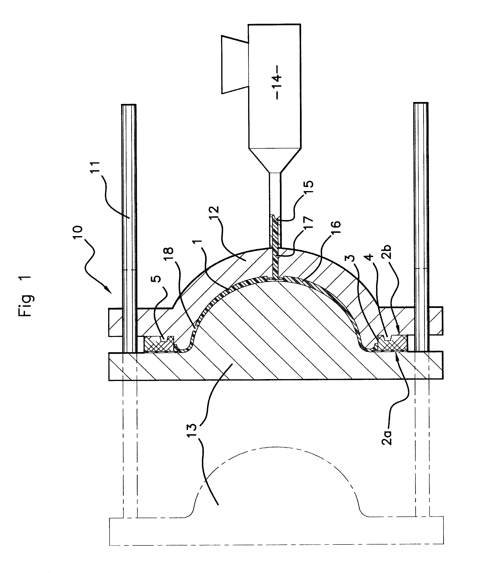
The invention aims to create a basin / receiving plane assembly that has improved reliability and resistance over time and is resistant to external stresses without sacrificing its appearance. This is achieved by adding indexing receptacles in the receiving plane that work with projections on the lower shell to position and hold the receiving plane in the injection mold. These projections also absorb the radial forces created by the injection process and prevent rupture of the receiving plane under the injection pressure.

Problems solved by technology

However, this technique, although it is satisfactory for producing single pieces, has numerous disadvantages when series production is envisaged.
Thus, the machining of the opening which requires great precision in the three dimensions to conform to the shape of the basin has a fairly large tolerance, due to the wear of the tools and the relative brittleness of the material when the plane consists of bonded wood particles.
Moreover, the use of various adhesive bonds and resin fillings necessitates waiting times (drying, polymerisation, etc.) and numerous manipulations (placing in a press for bonding, turning the planes over for casting the resin heel, etc.) which have an adverse effect on the quality and productivity during series production.

Method used


Image

  • Method for producing a basin integrated in a receiving plane, receiving plane for carrying out the method and monobloc assembly obtained by the method
  • Method for producing a basin integrated in a receiving plane, receiving plane for carrying out the method and monobloc assembly obtained by the method
  • Method for producing a basin integrated in a receiving plane, receiving plane for carrying out the method and monobloc assembly obtained by the method

Examples


first embodiment

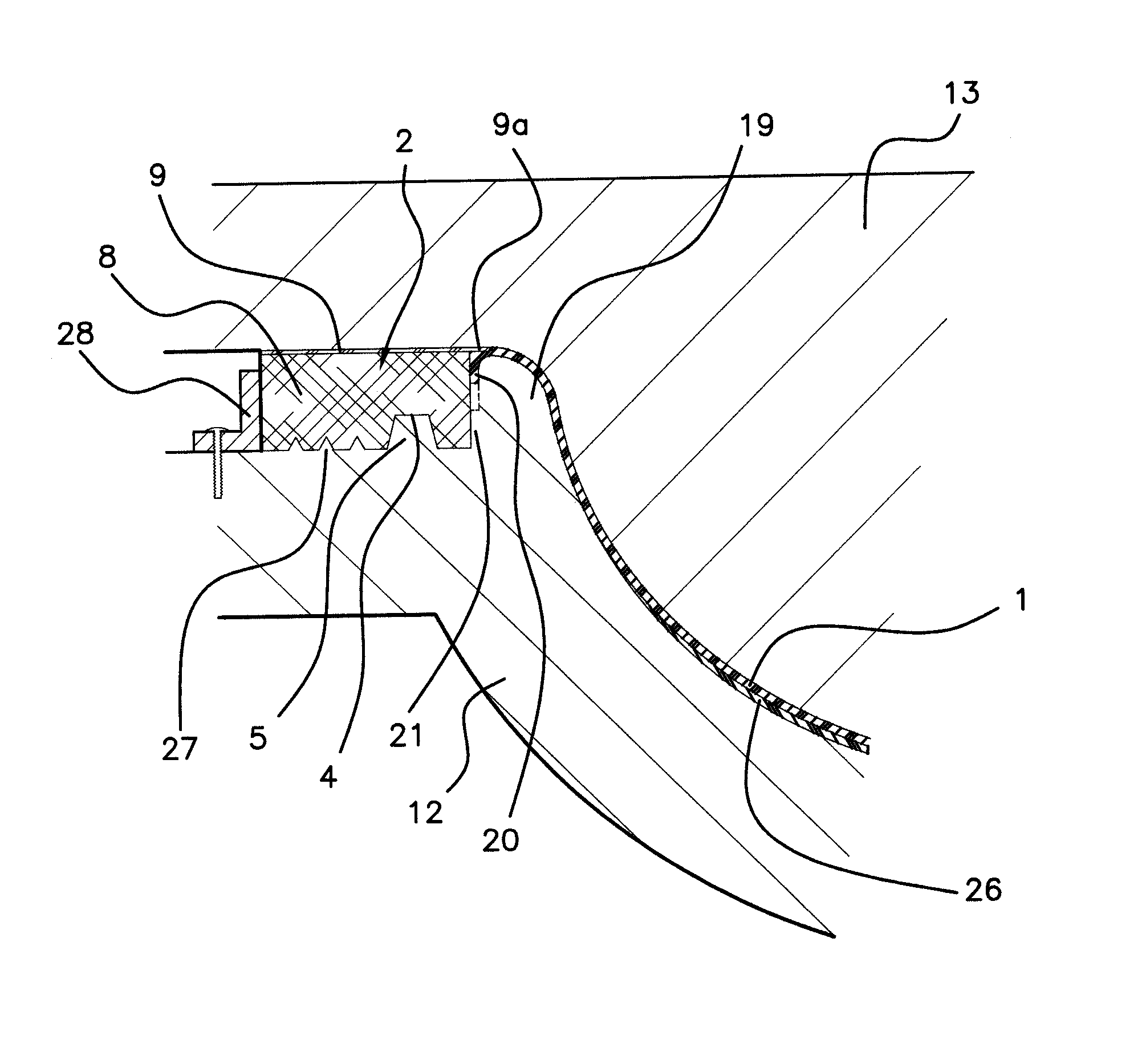
[0047]As will be seen below, the edge 3a of the opening 3 can have essentially two shapes: in the opening, illustrated in FIGS. 1, 2 and 4b, the edge 3a is made by a cutout substantially orthogonal to the planes of the main surfaces of the receiving plane. Advantageously, when the receiving plane 2 is formed by a supporting panel 8 and a decorative sheet 9, the cutting-out of the opening 3 is effected through the entire thickness of the supporting panel 8, leaving at least part of the decorative sheet 9 remaining, to form an overhang 9a above the opening.

second embodiment

[0048]In the opening, illustrated in FIGS. 3a, 3b and 4a, the edge 3a of the opening has a curved profile, substantially parallel to the shape of the wall of the basin.

[0049]Whatever the shape of the edge of the opening, the receiving plane 2 is then placed into an injection mould 10 for thermoplastic synthetic material in order to mould the basin 1 directly onto the receiving plane 2.

[0050]The mould 10 comprises a first shell which is called the lower shell 12 with reference to a top / bottom direction as defined above relative to the direction of the basin in the use position. The lower shell 12 has a central zone of generally concave shape adapted to form the bottom surface of the basin. At the periphery of the concave zone of the lower shell, the latter is adapted to bear in a planar manner on the lower surface 2b of the receiving plane and has projections 5 adapted to engage in the indexing receptacles 4 provided in the lower surface 2b of the receiving plane 2.

[0051]The mould 10...


PUM

PropertyMeasurementUnit
thicknessaaaaaaaaaa
thicknessaaaaaaaaaa
thicknessaaaaaaaaaa

Abstract

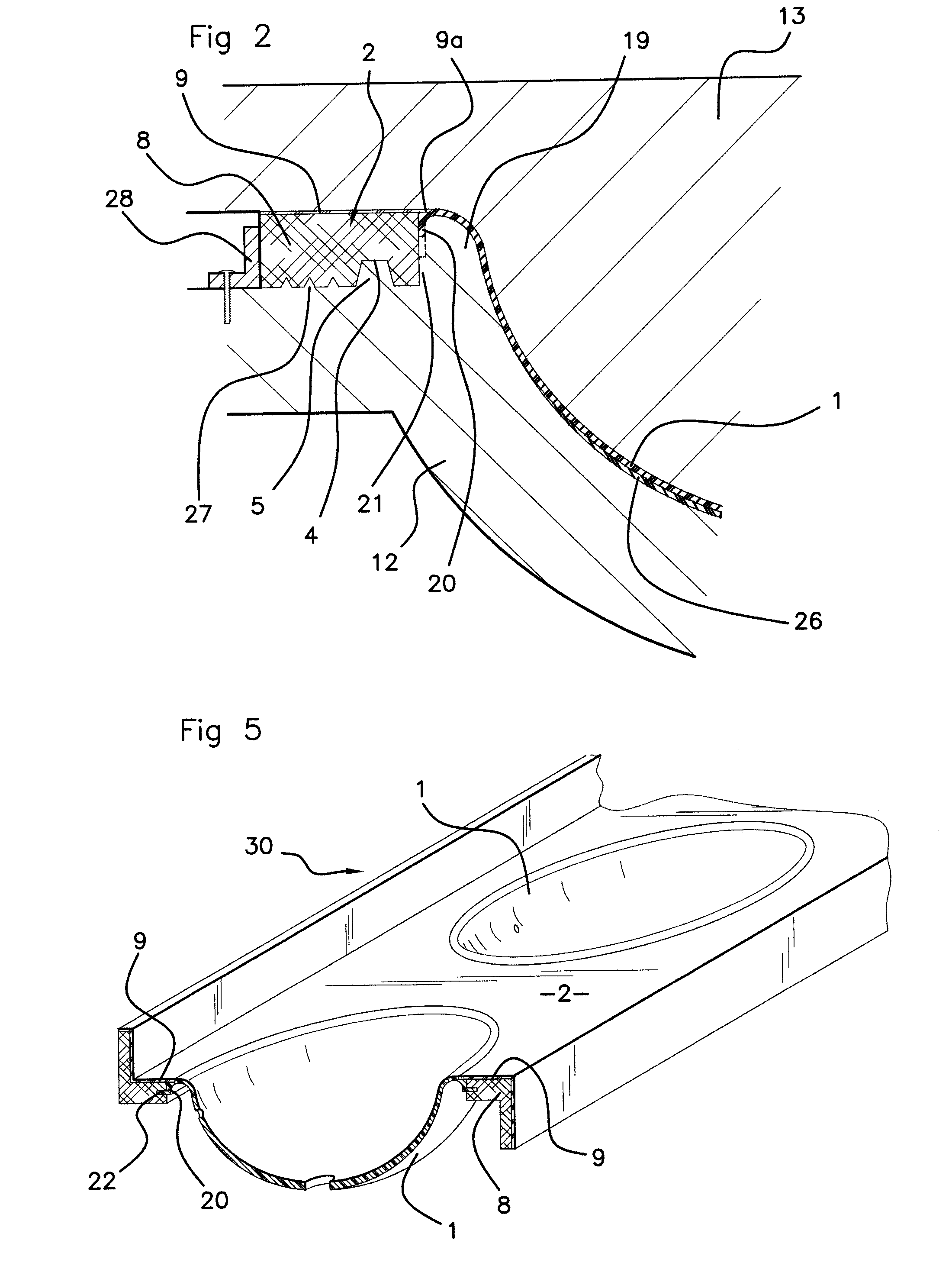
A method for producing a basin (1) integrated in a work plane, called the receiving plane (2), having an upper surface (2a) and a lower surface (2b), according to which method the receiving plane is pierced right through and an opening (3) adapted to receive the basin is formed, this receiving plane is installed in a mould (10) and the basin is moulded by injecting synthetic material directly onto the edge (3a) of the opening of the receiving plane. A receiving plane suitable for carrying out the method and a monobloc plane / basin assembly thus obtained are also described.

Description

BACKGROUND OF THE INVENTION[0001]The invention relates to a method for producing a monobloc assembly comprising a basin integrated in a receiving plane, in particular a sanitary surface or work surface of a bathroom or kitchen. It extends to a receiving plane used in this method and to the monobloc assembly thus obtained.DESCRIPTION OF THE RELATED ART[0002]Bathroom or kitchen furniture possesses an upper panel forming a sanitary or work surface, in which a basin, generally a sink or washbasin, is embedded; this upper panel may be clad with a covering (in particular made of laminate) and is often designated as a “receiving plane”. Two types of known techniques enable the basin to be integrated in the receiving plane. After an opening has been made in the latter, the basin can be put in place in said opening either from below the receiving plane or from above the latter.[0003]It is known, for example from the patent EP 1 076 740, to employ this second technique which makes it possible...

Claims


Application Information

Patent Timeline
Patent Type & Authority Patents(United States)
IPC IPC(8): E03C1/33B29C45/14B29C45/16B29K711/14B29L31/00E03C1/18
CPCB29C45/14336B29C45/14344B29C45/14778B29C45/1671E03C1/18E03C1/33B29C45/14311B29K2711/14B29L2031/7698Y10T428/24273
Inventor GALINIER, BENOIT
Owner CHENE VERT
Learn More