Medicinal solution injection device and medicinal solution injection method
a technology of injection device and medicinal solution, which is applied in the direction of pharmaceutical containers, packaging foodstuffs, packaged goods, etc., can solve the problems of imposing even more time-consuming and complex work load on medical personnel, and imposing heavy time-consuming and labor-intensive medical personnel, so as to prevent the foaming of medicinal solution, the effect of accurately and efficiently injecting the medicinal solution
- Summary
- Abstract
- Description
- Claims
- Application Information
AI Technical Summary
Benefits of technology
Problems solved by technology
Method used
Image
Examples
embodiment 1
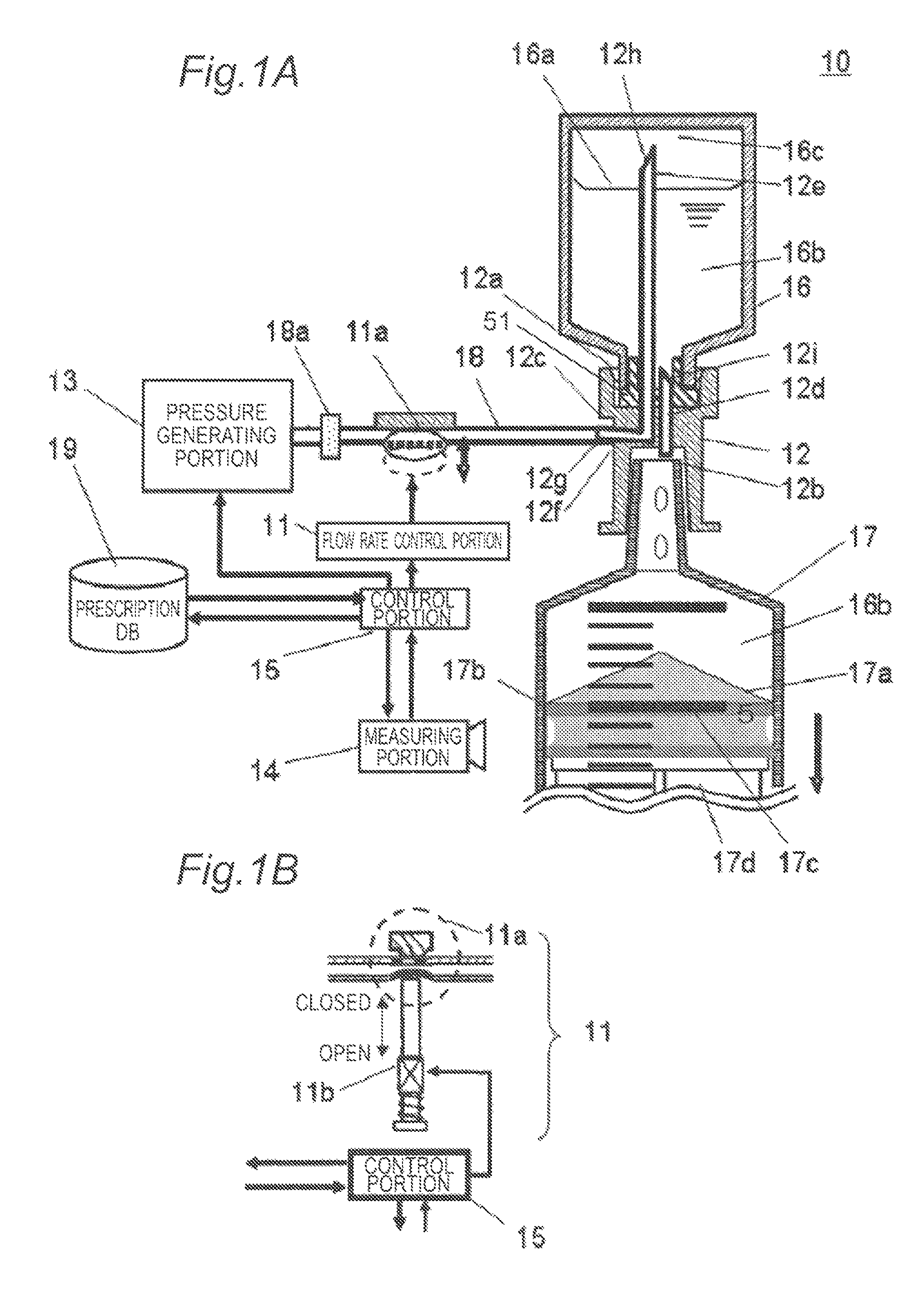
[0030]FIGS. 1A and 1B are schematic illustrations of a medicinal solution injection apparatus 10 according to an embodiment 1 of the present invention. FIG. 1A is a side view schematically illustrating an overall structure of the medicinal solution injection apparatus 10. FIG. 1B is an enlarged view of a flow rate control portion 11.
[0031]As illustrated in FIGS. 1A and 1B, the medicinal solution injection apparatus 10 according to the embodiment 1 is provided with a composite needle 12 for injecting a medicinal solution, a pressure generating portion 13 configured to discharge a compressed gas, a flow rate control portion 11 configured to control a flow rate of the compressed gas, a measuring portion 14 configured to measure a filling amount and a filling speed of the medicinal solution, and a control portion 15. The control portion 15 controls the pressure generating portion 13, flow rate control portion 11, and measuring portion 14.
[0032]The composite needle 12 has a needle base p...
embodiment 2
[0079]FIG. 8 is a side view schematically illustrating an overall structure of a medicinal solution injection apparatus 20 according to an embodiment 2 of the present invention.
[0080]Similarly to the medicinal solution injection apparatus 10 according to the embodiment 1, the medicinal solution injection apparatus 20 according to the embodiment 2 is provided with the composite needle 12 for injecting the medicinal solution, the pressure generating portion 13 configured to discharge the compressed gas, the flow rate control portion 11 configured to control the flow rate of the compressed gas, the measuring portion 14 configured to measure the filling amount and the filling speed of the medicinal solution 16b, and the control portion 15 configured to control the pressure generating portion 13, flow rate control portion 11, and measuring portion 14, as illustrated in FIG. 8.
[0081]The edge 12h of the adjustment needle 12e is inserted into the vial container 16 above the liquid surface 1...
embodiment 3
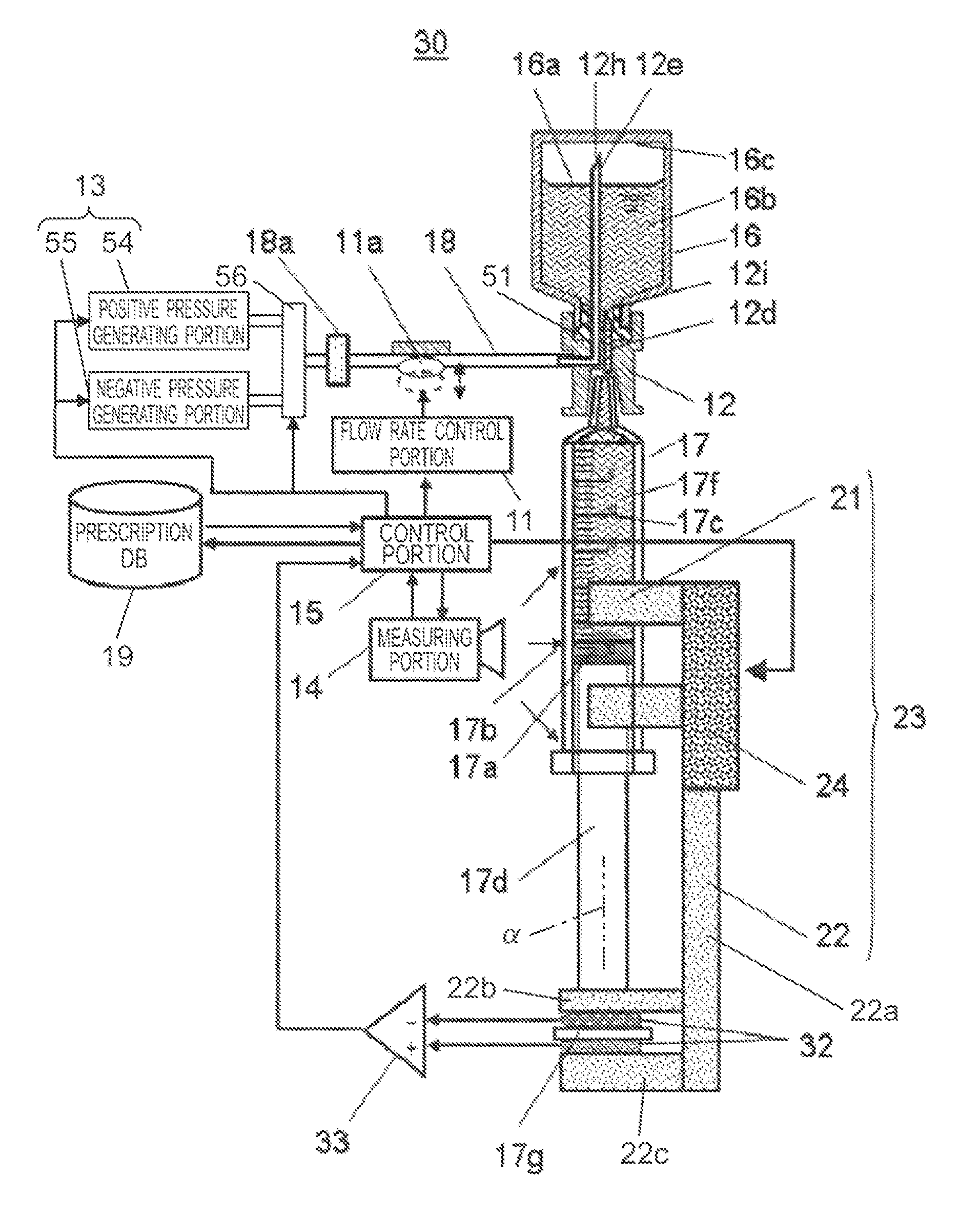
[0096]FIG. 13 is a side view schematically illustrating an overall structure of a medicinal solution injection apparatus 30 according to an embodiment 3 of the present invention.
[0097]Similarly to the medicinal solution injection apparatus 20 according to the embodiment 2, the medicinal solution injection apparatus 30 according to the embodiment 3 is provided with the composite needle 12 for injecting the medicinal solution, the measuring portion 14 configured to measure the filling amount and the filling speed of the medicinal solution, a pressure generating portion 13, and the control portion 15 configured to control the pressure generating portion 13, flow rate control portion 11, and measuring portion 14, as illustrated in FIG. 13. The pressure generating portion 13 of the medicinal solution injection apparatus 30 has a pressure application function for discharging the compressed air and a pressure reduction function for reducing the pressure of the compressed air to a pressure ...
PUM
| Property | Measurement | Unit |
|---|---|---|
| filling speed | aaaaa | aaaaa |
| inner diameter | aaaaa | aaaaa |
| sliding movement | aaaaa | aaaaa |
Abstract
Description
Claims
Application Information
 - R&D
- Intellectual Property
- Life Sciences
- Materials
- Tech Scout
- Unparalleled Data Quality
- Higher Quality Content
- 60% Fewer Hallucinations
Browse by: Latest US Patents, China's latest patents, Technical Efficacy Thesaurus, Application Domain, Technology Topic, Popular Technical Reports.
© 2025 PatSnap. All rights reserved.Legal|Privacy policy|Modern Slavery Act Transparency Statement|Sitemap|About US| Contact US: help@patsnap.com


