
Differential step size optimization method for dynamic optimal energy flow calculation of cogeneration system

A technology of energy flow calculation and system dynamics, applied in the direction of AC networks with the same frequency from different sources, can solve problems such as the surge in the dimension of constraint sets, the increase in the complexity of optimal energy flow calculations, and the loss of reference value of optimization results, etc., to achieve The effect of efficient and accurate solution

Active Publication Date: 2022-07-15
SOUTHEAST UNIV
View PDF1 Cites 0 Cited by
  • Summary
  • Abstract
  • Description
  • Claims
  • Application Information

AI Technical Summary

Problems solved by technology

On the one hand, if the difference step size is too large, there will be a large difference between the system simulation results and the actual operation results, and the optimization results will lose the reference value; on the other hand, if the difference step size is too small, it will cause the entire optimization model The dimensionality of the constraint set increases rapidly, which increases the complexity of the optimal energy flow calculation, and it is difficult to obtain the optimal energy flow of the system under limited computing resources and computing time

Method used


Image

  • Differential step size optimization method for dynamic optimal energy flow calculation of cogeneration system
  • Differential step size optimization method for dynamic optimal energy flow calculation of cogeneration system
  • Differential step size optimization method for dynamic optimal energy flow calculation of cogeneration system

Examples


Embodiment 1

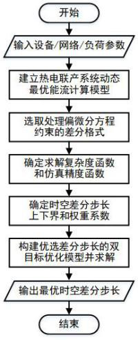
[0056] Differential step size optimization method for dynamic optimal energy flow calculation of cogeneration system, such as figure 1 shown, including the following steps:

[0057] S1, establish a dynamic optimal energy flow calculation model of the cogeneration system: the cogeneration system uses hot water as the heat medium of the heat network, and the heat network adopts a quality adjustment operation mode, and the dynamic optimal energy flow calculation model includes The thermal network dynamic power flow constraint is a set of partial differential equation constraints with the temperature of the heat medium as a variable:

[0058]

[0059] In the formula: T represents the temperature of the heat medium in the pipeline; t and x represent the time variable and space variable respectively; T amb Indicates the ambient temperature outside the pipe; v and c represent the mass flow rate, flow rate and specific heat capacity of the heat medium, respectively; R represents...


PUM


Abstract

The patent of the present invention discloses a differential step size optimization method for calculating the dynamic optimal energy flow of a cogeneration system. First, a calculation model of the optimal energy flow of the cogeneration system including the dynamic power flow constraints of the heat network is established. The dynamic power flow constraint is a set of partial differential equation constraints with the temperature of the heat medium as a variable; secondly, the differential scheme to deal with the partial differential equation constraints is selected, and the selected differential scheme satisfies unconditional stability and convergence; then the above optimal algorithm is determined according to the selected optimization algorithm. The solution complexity function of the energy flow calculation model, the simulation accuracy function is determined according to the selected difference format; finally, the weight coefficients of the calculation complexity function and the simulation accuracy function are respectively determined according to the application of the dynamic optimal energy flow, and the construction is comprehensively considered to minimize A dual-objective optimization model with computational complexity and maximizing simulation accuracy, and the optimal differential step size is selected according to the optimization results; this method can select the optimal differential step size that takes into account both computational complexity and simulation accuracy, and is implemented under certain computing resources. Efficient and accurate solution of dynamic optimal energy flow in cogeneration systems.

Description

technical field [0001] The invention belongs to the technical field of energy system operation optimization, and in particular relates to a differential step size optimization method for dynamic optimal energy flow calculation of a cogeneration system. Background technique [0002] With the increasing negative impact of climate change and environmental pollution, countries around the world are exploring new forms of clean, efficient and sustainable energy utilization. In this context, the European Union proposed to build a "pan-European network" of smart energy; the United States and Japan also proposed a "hydrogen energy plan" and a "comprehensive energy plan" to change the way energy is used. Carrying out research on multi-energy complementary core technologies is in line with the major needs of my country's energy strategy. The state vigorously advocates the development of energy Internet, smart energy and multi-energy complementation, and actively promotes The theoretica...

Claims


Application Information

Patent Timeline
Patent Type & Authority Patents(China)
IPC IPC(8): H02J3/06
CPCH02J3/06
Inventor 顾伟姚帅陆帅周苏洋吴志潘光胜张苏涵
Owner SOUTHEAST UNIV
Learn More