Supercharge Your Innovation With Domain-Expert AI Agents!

Method for detecting with a high temporal accuracy a threshold crossing instant by a signal

a detection method and high temporal accuracy technology, applied in the direction of time interval measurement without driving mechanism, time interval measurement with driving mechanism, timer, etc., can solve the problems of less and less use of analog detection methods, and the inability to have numerical results and outcomes, etc., to achieve high temporal accuracy and reduce temporal detection error

Inactive Publication Date: 2015-01-13
THALES ITALA
View PDF8 Cites 0 Cited by
  • Summary
  • Abstract
  • Description
  • Claims
  • Application Information

AI Technical Summary

Benefits of technology

This approach significantly reduces temporal detection errors to be much lower than the clock period, enhancing accuracy by one to two orders of magnitude, making it suitable for precise applications like radar and GPS systems with reduced complexity and cost.

Problems solved by technology

In this case, however, the detection accuracy of the time of arrival is related to noise and thermal drift features of the analog circuits that are used.
The analog detection method, actually, is less and less used, because of the accuracy limitations due to the reasons mentioned above.
Moreover, the analog nature of such method does not allow having numerical results and outcomes and therefore it cannot be used in the field of digital electronics, nowadays prevailing.
Due to their digital nature, said methods intrinsically exhibit a temporal discretization which limits the accuracy that may be obtained in the detection.
Ideally, a clock operating at very high frequencies (thus with a very short clock period) would ensure a good resolution but would give rise to a circuit complexity, to signal integrity problems, to energy consumptions and to costs not compatible with realistic solutions.
On the other hand, the use of clocks with cost and complexity compatible with the scope considered (for example, having a clock period in the order of 10 ns) limits the temporal resolution of the detection of the threshold crossing instant: the order of magnitude of such resolution is comparable to the clock period.
As a consequence, the detection error margin, comparable to the clock period, may be unsatisfactory for many applications, such as the already mentioned reception and transmission systems for radars or for GPS localizers.

Method used


Image

  • Method for detecting with a high temporal accuracy a threshold crossing instant by a signal
  • Method for detecting with a high temporal accuracy a threshold crossing instant by a signal
  • Method for detecting with a high temporal accuracy a threshold crossing instant by a signal

Examples


first embodiment

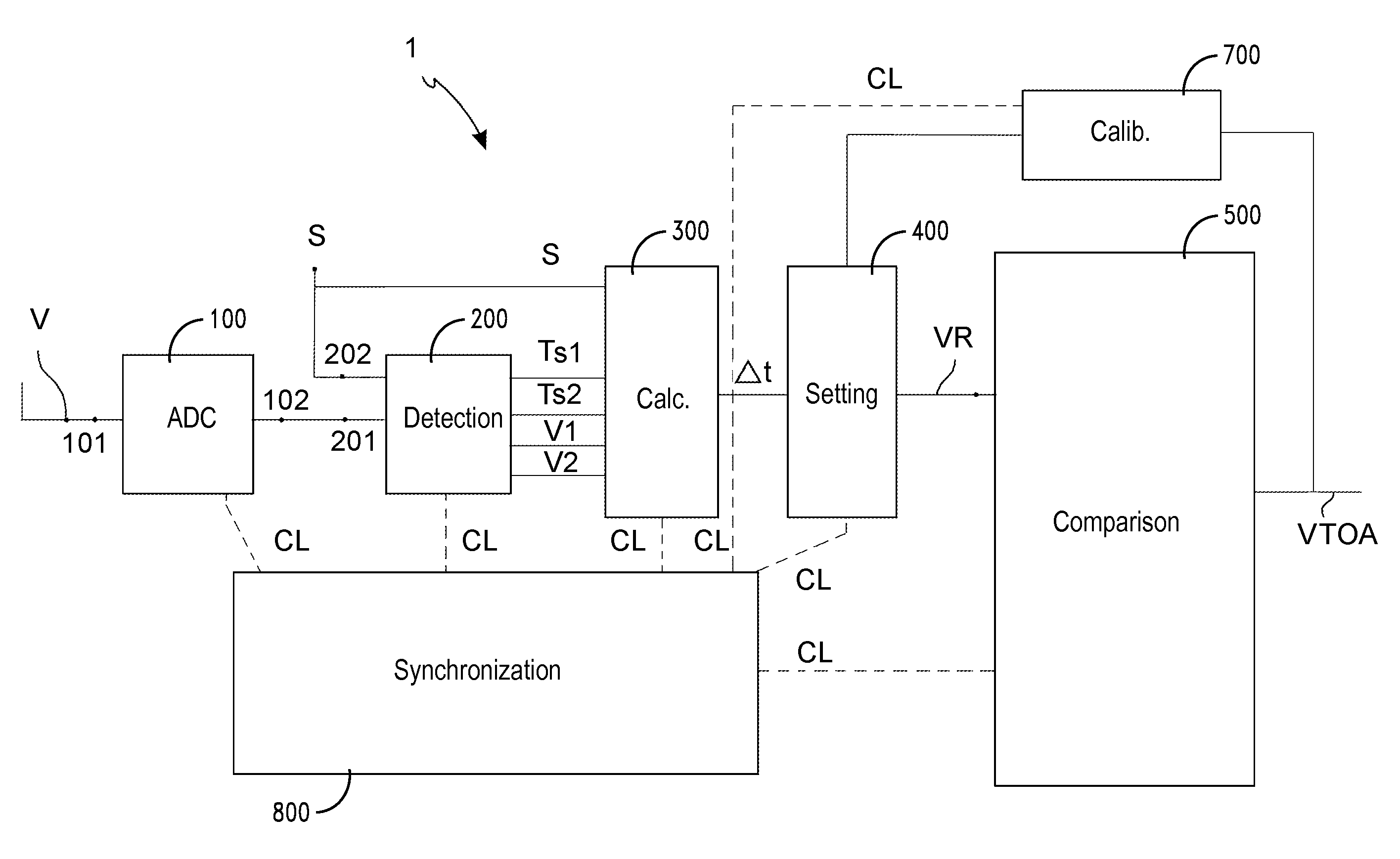
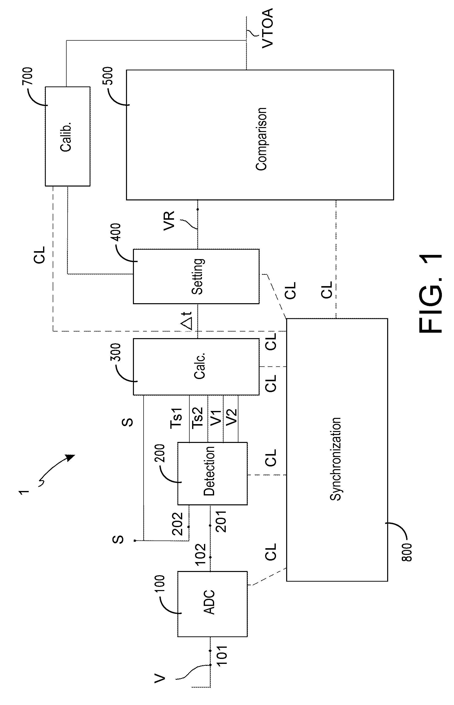
[0134] the disclosure comprises a method for detecting, through an electronic detection device 1, a threshold crossing instant TOA at which an electrical signal V crosses a threshold S, comprising the following steps: defining a sequence of discrete clock instants Tn by a clock signal CL, such that two consecutive clock instants of the sequence are spaced in time from one another by a clock period T; then, sampling the electrical signal V with a sampling period T equal to the clock period T, in a plurality of sampling instants Ts belonging to the sequence of clock instants Tn; then detecting a first sampling instant Ts1 and a subsequent consecutive second sampling instant Ts2, such that at one of said first Ts1 and second Ts2 sampling instant the sampled signal value has a first signal value V1 lower than, or equal to, threshold S, and at the other one of said first Ts1 and second Ts2 sampling instant the sampled signal value has a second signal value V2 higher than threshold S; mor...

second embodiment

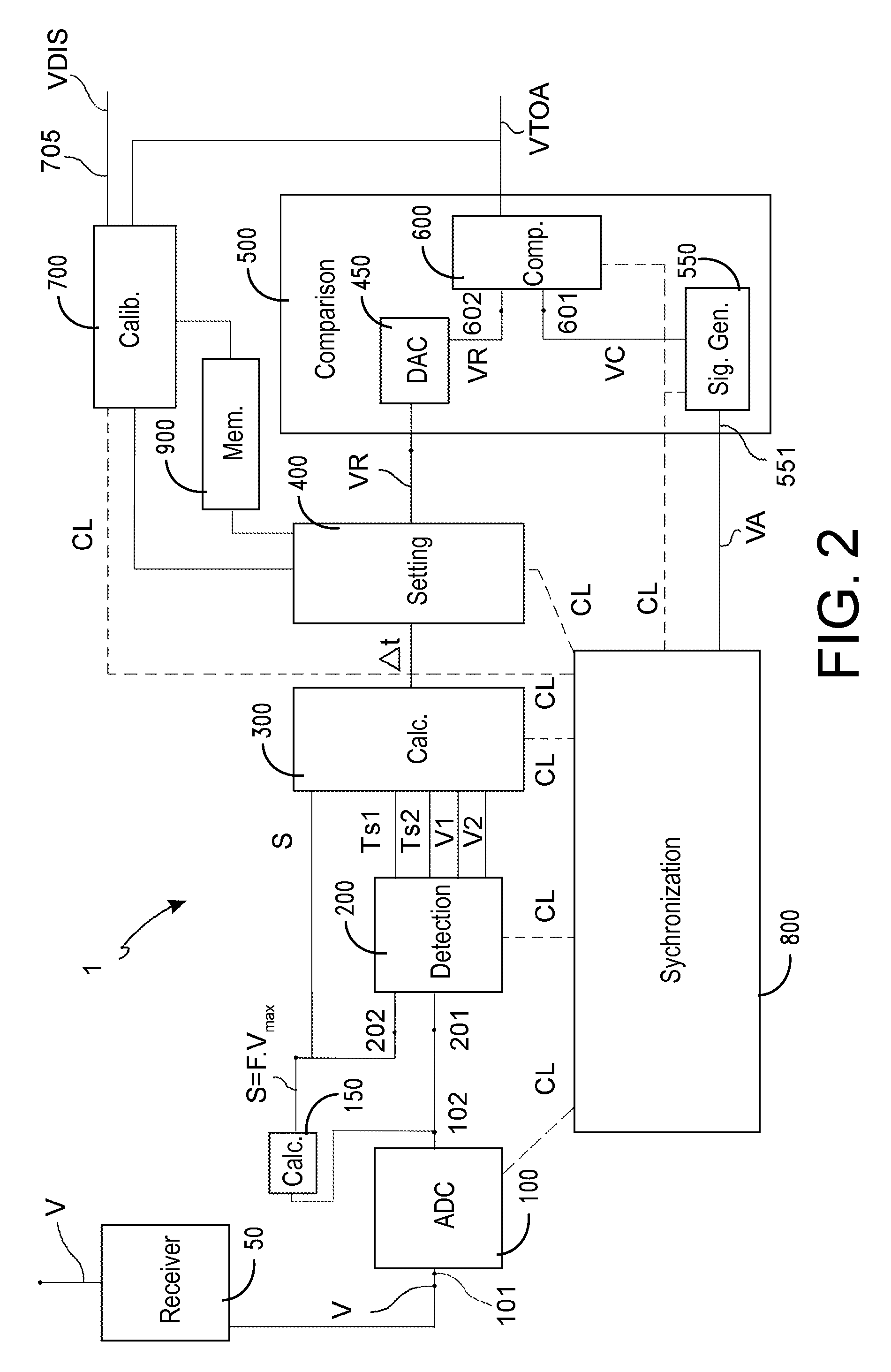
[0135] the method provides that the step of calibrating further comprises the following steps: firstly, providing a sequence of test reference electrical signals to the module with controlled delay 500; then, determining a minimum test reference signal amplitude for which the comparison module 500 generates the threshold crossing detection signal TTOA synchronized with the reference instant Tr; likewise, determining a maximum test reference signal amplitude for which the module with controlled delay 500 generates the threshold crossing detection signal TTOA with a delay equal to the clock period T relative to the reference instant Tr; finally, defining the reference scale of the reference amplitude VR on the basis of said maximum amplitude and minimum amplitude of test reference.

third embodiment

[0136] the method provides that the step of calibrating further comprises, on the contrary, the following steps: defining the reference scale of the reference amplitude VR on the basis of a reference amplitude range ΔVR between a minimum reference amplitude VRmin and a maximum reference amplitude VRmax; then, calculating the reference amplitude VR, depending on the time interval Δt, so that the reference amplitude VR and the minimum reference amplitude VRmin define a reference difference such that the ratio between said reference difference and the reference amplitude range ΔVR is substantially equal to the ratio between the first time interval Δt and the clock period T. According to such embodiment, moreover, the comparison module 500 is configured for generating the threshold crossing detection signal VTOA with a delay linearly depending on the reference amplitude VR. It should be noted that, in this embodiment of the method, the above illustrated formula (7) is used.

[0137]A furth...


PUM


Abstract

A method detects a threshold crossing instant at which a signal crosses a threshold, by: sampling the signal at plural sampling instants spaced from one another by a sampling period; detecting consecutive first and second sampling instants at which the signal has a first signal value lower than or equal to the threshold, and the signal has a second signal value higher than the threshold, respectively; calculating a first interval indicative of a time between the threshold crossing instant and the first sampling instant; setting a reference signal having a reference amplitude representing the first interval relative to a reference scale; generating a signal with a delay depending on said reference signal; generating a threshold crossing detection signal at an instant delayed by a second interval; calibrating the reference scale of the reference amplitude so that the second interval is substantially equal to the first interval.

Description

BACKGROUND[0001]1. Technical Field[0002]The present disclosure relates to the detection of a threshold crossing instant by an electrical signal, by means of an electronic device. In particular, the disclosure relates to a method and a device capable of detecting, with a high temporal accuracy, a threshold crossing instant of an electrical signal converted in digital form.[0003]2. Description of the Related Art[0004]In several electronic systems, it is essential to detect an instant at which an electrical signal crosses a threshold level, or threshold.[0005]The threshold crossing may be representative, in different application scopes, of different events: for example, it may be associated to a change in the digital logical level, or it may discriminate a condition of signal “absence” (off) from a condition of signal “presence” (on), or vice versa.[0006]In particular, for an electrical signal having a monotonic leading or trailing edge, the crossing instant of a threshold may represen...

Claims


Application Information

Patent Timeline
Patent Type & Authority Patents(United States)
IPC IPC(8): H04B3/46H03K5/08H03K5/1534H04B17/00
CPCH03K5/08H03K5/1534H04B17/00H04B17/17
Inventor CASTI, MAURIZIO
Owner THALES ITALA
Features
  • R&D
  • Intellectual Property
  • Life Sciences
  • Materials
  • Tech Scout
  • Unparalleled Data Quality
  • Higher Quality Content
  • 60% Fewer Hallucinations
Learn More