Transmitter with peak-tracking PAPR reduction and method therefor

a technology of papr reduction and transmitter, which is applied in the field of radiofrequency (rf) communication systems, can solve the problems of nonlinearity, nonlinearity, nonlinearity, and spectral regrowth, and all linear rf power amplifiers invariably fail to meet,

Inactive Publication Date: 2015-01-13
CRESTCOM INC
View PDF25 Cites 11 Cited by
  • Summary
  • Abstract
  • Description
  • Claims
  • Application Information

AI Technical Summary

Problems solved by technology

While perfect linearity is a goal for any linear RF power amplifier, all linear RF power amplifiers invariably fail to meet it.
The degree to which the goal of perfect linearity is missed leads to unwanted intermodulation, nonlinearities, and spectral regrowth.
As transmitter technology has advanced, and as increasing demands have been placed on the scarce resource of the RF spectrum by the public, the spectral masks have become increasingly strict.
In conventional RF transmitters, the amplifier linearity requirement is usually difficult to achieve at a reasonable cost.
In general, more sophisticated and expensive amplifiers can be devised which exhibit better linearity.
In conventional RF transmitters, the amplifier linearity and cost parameters are counterbalanced against power-added efficiency (PAE).
An amplifier that has low PAE wastes power, which is undesirable in any transmitter, but particularly undesirable in battery-powered transmitters because it necessitates the use of undesirably large batteries and / or undesirably frequent recharges.
Another factor that affects costs, linearity, and PAE is an RF amplifier's dynamic range.
An amplifier that is required to have a large dynamic range and to faithfully reproduce a communication signal with occasional large peaks also tends to be more expensive and exhibit less PAE than amplifiers that are not required to have such a large dynamic range.
And, if the amplifier simply does a poor job of reproducing the peaks, then linearity suffers.
In theory, accurately following the RF communication signal's envelope over a higher bandwidth would achieve greater PAE improvements, but in practice it would require the use of such an expensive power supply that any cost savings in the RF amplifier would be lost.
Moreover, a large amount of power is likely to be consumed by such a higher bandwidth power supply, and additional unwanted RF noise is likely to be generated.
Unfortunately, dynamic amplifier bias control does nothing to lessen dynamic range constraints for the RF amplifier.
But, these beneficial power amplifier consequences come at the cost of introducing more noise into the communication signal.
Unfortunately, conventional PR circuits with lagging-indicator signal magnitude threshold signals tend to reduce peaks in a way that is too imprecise and is largely incompatible with dynamic amplifier bias control.
In other words, power savings and PAE improvements may be achieved through dynamic amplifier bias control, and similar improvements may be achieved by using a PR circuit, but using both conventional dynamic amplifier bias control and a conventional PR circuit tends to introduce no significant further improvements to those achievable using either one alone.

Method used


Image

  • Transmitter with peak-tracking PAPR reduction and method therefor
  • Transmitter with peak-tracking PAPR reduction and method therefor
  • Transmitter with peak-tracking PAPR reduction and method therefor

Examples


Embodiment Construction

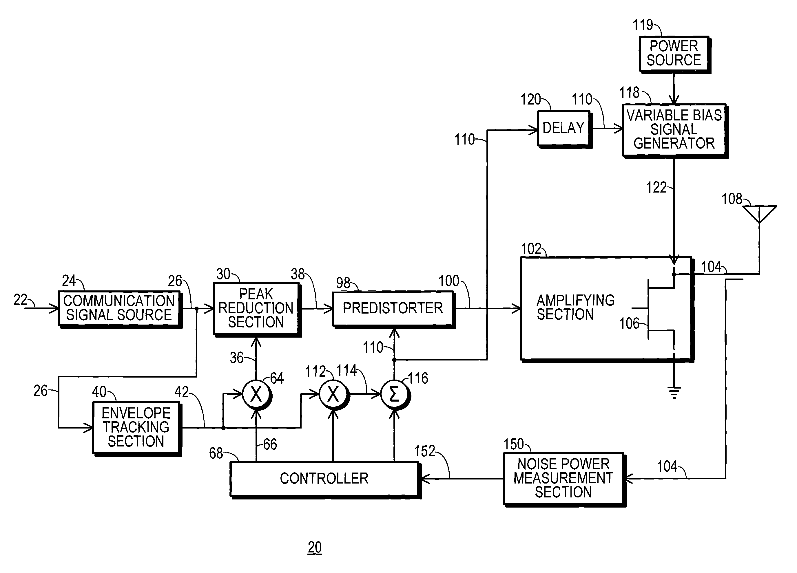
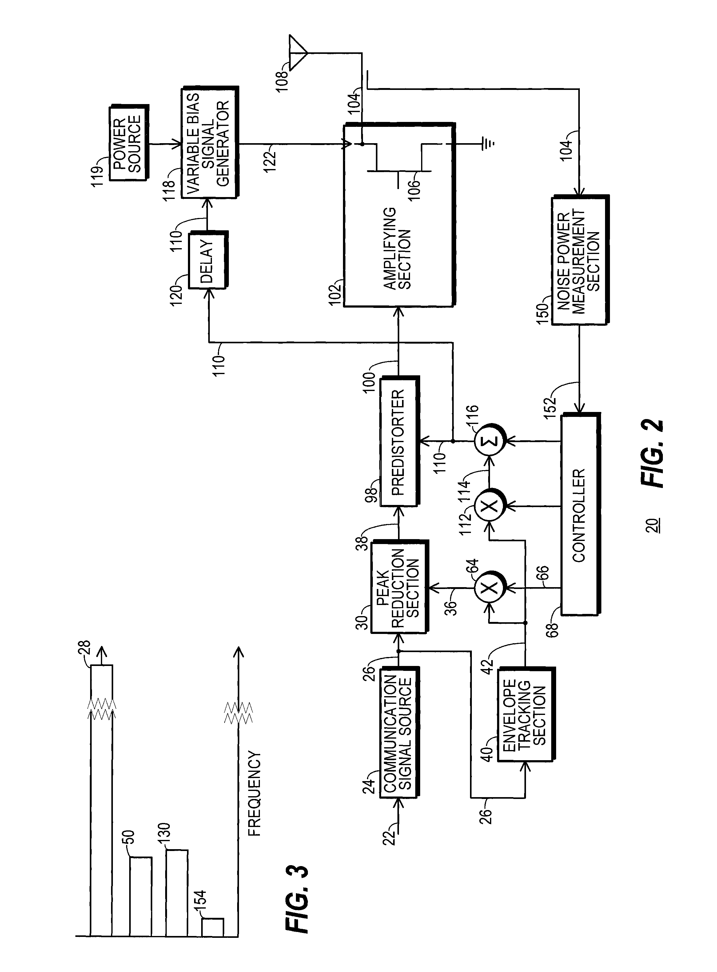
[0033]FIG. 2 shows a simplified block diagram of a transmitter 20 configured in accordance with one embodiment of the present invention. In the embodiment explicitly depicted in the figures, transmitter 20 is configured to wirelessly transmit an RF communication signal. But those skilled in the art will appreciate that the present invention may also be used in other types of communication systems, including a communication system that transmits optical signals through an optical transmission medium, a system that transmits signals to a magnetic recording medium, and in other applications, such as audio amplification.

[0034]Transmitter 20 receives one or more raw data streams 22 at an input to a communication signal source 24. Communication signal source 24 provides a digitally modulated, complex, baseband version of an inflated-peak communication signal 26. A communication signal, such as inflated-peak communication signal 26 and others discussed below, is an electronic signal that m...


PUM


Abstract

A transmitter (20) includes a peak reduction section (30), a predistorter (98), and an amplifying section (102) biased by a variable bias signal generator (118). The peak reduction section (30) is controlled by a signal magnitude threshold (36) that defines maximum magnitudes for local peaks (32) of a reduced-peak communication signal (38). The bias signal generator (118) is controlled by a bias control signal (110). Both the signal magnitude threshold (36) and the bias control signal (110) are derived from a common reduced bandwidth (50) peak-tracking signal (42). The peak-tracking signal (42) is derived from an inflated-peak communication signal (26). The predistorter (98) applies distortion to the reduced-peak communication signal (38) that is configured, at least in part, by the bias control signal (110).

Description

TECHNICAL FIELD OF THE INVENTION[0001]The present invention relates generally to the field of radio-frequency (RF) communication systems. Specifically, the present invention relates to transmitters that include circuits and / or processes for the purpose of reducing peak-to-average power ratio (PAPR) in communication signals and that include circuits and / or processes to dynamically control RF amplifier bias signals.BACKGROUND OF THE INVENTION[0002]An RF power amplifier provides the final stage of amplification for a communication signal that has been modulated and converted into an RF signal. Often that RF signal exhibits frequencies in a predetermined frequency band that is licensed by a regulatory agency for a particular use. The RF power amplifier boosts the power of this RF communication signal to a level sufficient so that the signal, when it propagates to an antenna, will be broadcast in such a manner that it will meet the communication goals of the RF transmitter.[0003]Many pop...

Claims


Application Information

Patent Timeline
Patent Type & Authority Patents(United States)
IPC IPC(8): H04B1/04H04B17/00
CPCH04L27/2614H03F1/3247H03F1/0266H03F3/193H03F3/245H03F2200/102
Inventor MCCALLISTER, RONALD DUANE
Owner CRESTCOM INC
Why Eureka
Try Eureka