Radio frequency based ablation system and method with dielectric transformer

a dielectric transformer and radio frequency technology, applied in the field of radio frequency based ablation system for ablating tissue and occlusions, can solve the problem of preventing the maximum performance of the fixed electromagnetic rf supply circui

Active Publication Date: 2015-01-13
MEDWAVE INC
View PDF18 Cites 27 Cited by
  • Summary
  • Abstract
  • Description
  • Claims
  • Application Information

AI Technical Summary

Benefits of technology

[0011]This arrangement creates a space or transition area between the emitting arm of the antenna and the return arm or outer tubular member of the device, providing an intentional discontinuity. This reduces the dependence of the system on tissue parameters, by providing a single-ended driver circuit.
[0013]In yet another embodiment, a tissue ablation device is provided in which a gradual transition point is provided from the coaxial cable of the device and the antenna tip, by means of a plurality of dielectric layers which terminate at longitudinally spaced location from the cable to the tip of the device. This gradual transition mitigates the mode conversion loss due to the change from the tranverse electromagnetic mode (TEM) mode of propagation in the coaxial cable to the mode pattern of the electromagnetic field propagating in the tissue, reducing localized heating effects which can occur with abrupt transitions.

Problems solved by technology

This prevents a fixed electromagnetic RF supply circuit from achieving maximum performance in delivering the highest amount of RF energy to the tissue being treated.

Method used


Image

  • Radio frequency based ablation system and method with dielectric transformer
  • Radio frequency based ablation system and method with dielectric transformer
  • Radio frequency based ablation system and method with dielectric transformer

Examples


Embodiment Construction

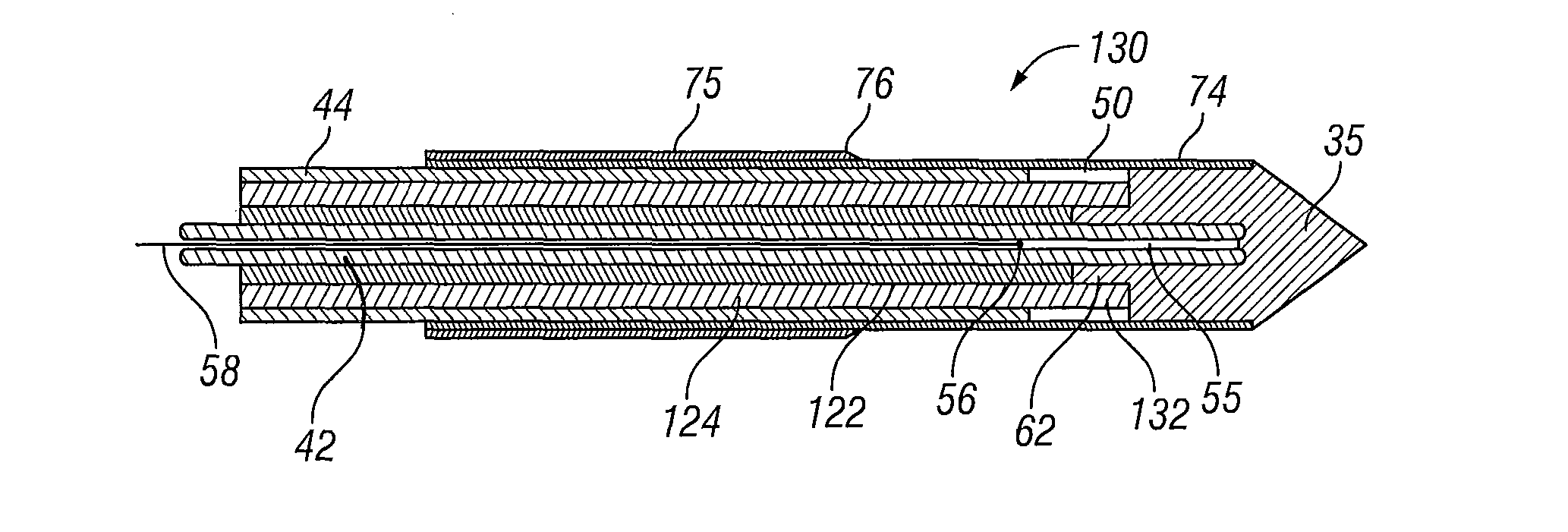
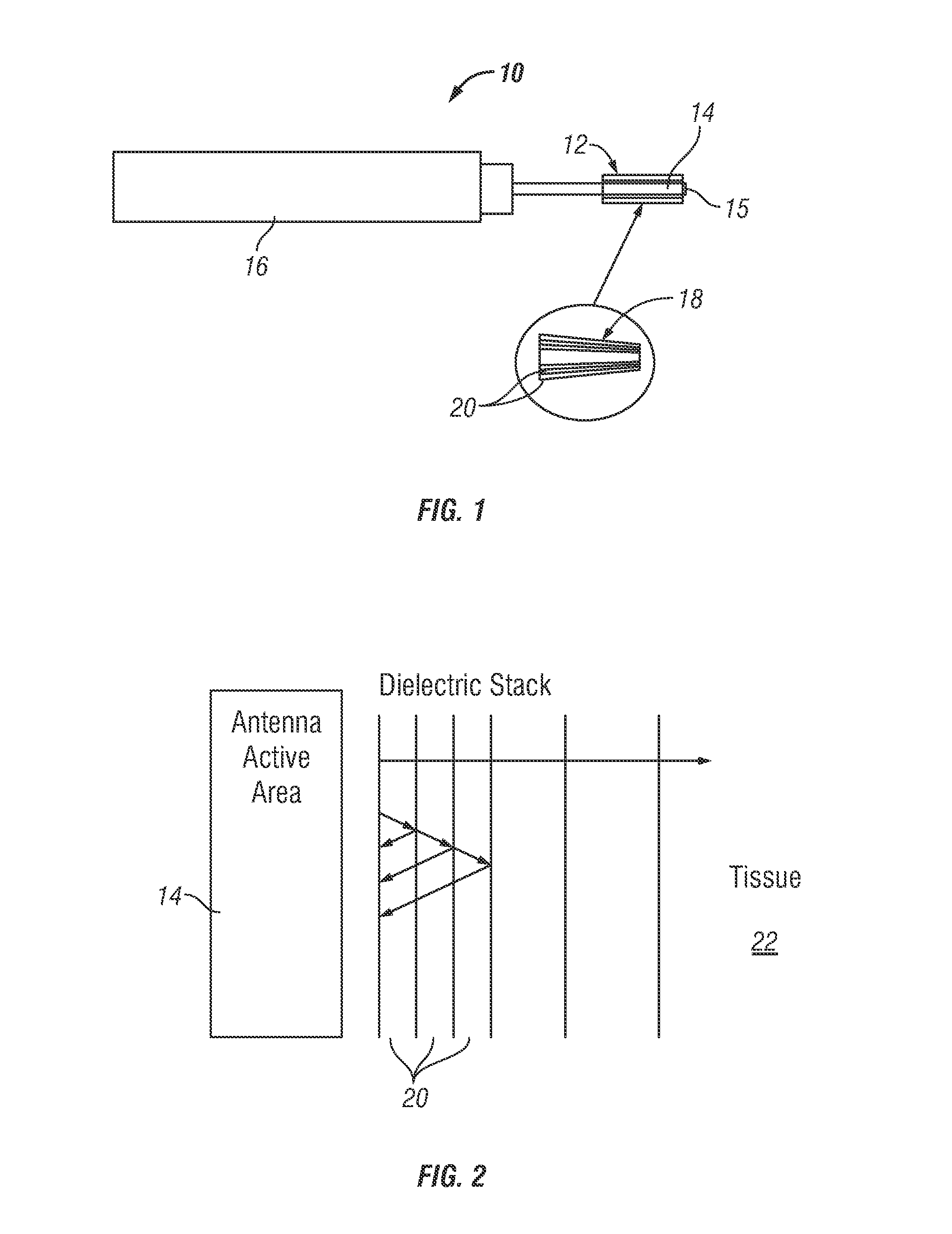
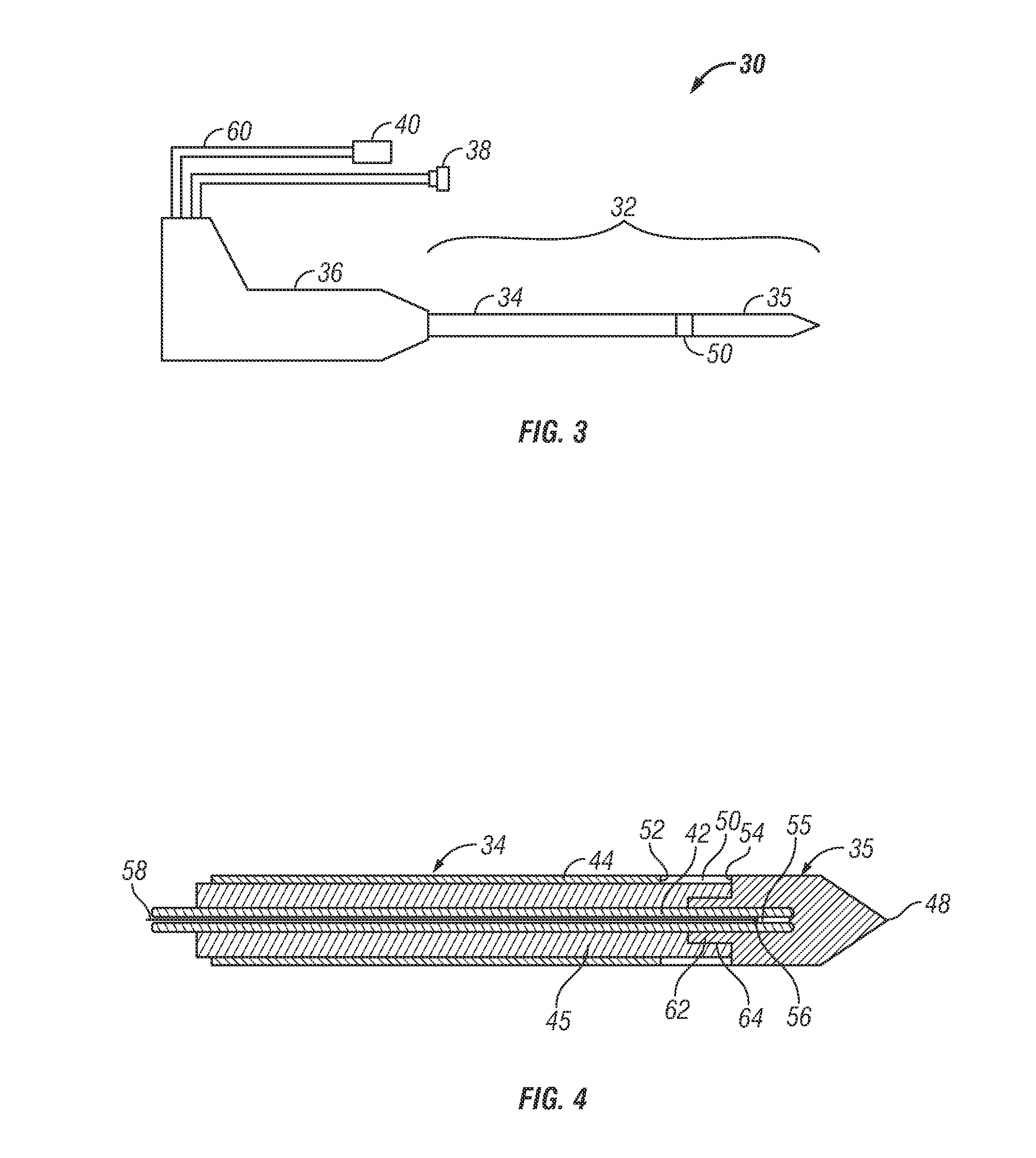
[0030]Certain embodiments as disclosed herein provide for a radio frequency energy transmission device, which incorporates a wave guide for conducting radio frequency (RF) energy, particularly microwave energy, for the ablation of biological tissues. The wave guide has an outer tubular conductor and an inner conductor within the lumen of the outer conductor which extends up to a distal portion of the device. An ablating member such as a radio frequency (RF) antenna which delivers radio frequency energy, particularly microwave energy, is located at the distal portion of the wave guide. Various arrangements are provided for improving coupling of energy into the tissue to be treated are provided in the different embodiments, including a dielectric stack around the antenna, a spacer or discontinuity in one of the cables connected to the antenna, and a longitudinal dielectric transformer to provide a gradual transition point from the coaxial cable to the transformer.

[0031]After reading t...


PUM


Abstract

An ablation device which transmits radio frequency (RF) energy for the ablation of biological tissues has elongate inner and outer coaxial conductors extending from a proximal portion to a distal portion. An RF antenna is disposed at the distal portion of the device and transmits RF energy for ablation of a tissue region to be treated. Reflection of energy from the tissue or the ablation point is reduced by providing multiple layers of dielectric media about the antenna, or by providing a gradual transition point from the conductors to the antenna tip, by means of a longitudinally stepped dielectric layer transformer.

Description

BACKGROUND[0001]1. Field of the Invention[0002]The present invention concerns a radio frequency (RF) based system for ablating tissue and occlusions, particularly within liquid-filled lumens of animals, such as the heart, liver, arteries and vessels of a human, with an electrical field produced about an RF antenna, and is particularly concerned with reducing reflected signal losses in such a system.[0003]2. Related Art[0004]Therapeutic tissue ablation systems apply energy to a biological ablation tissue site via different energy exchange means, such as heat conduction and irradiation. These systems may employ various energy modes, such as radiofrequency, ultrasound, laser, cryogenic, and the like. Within the radio frequency (RF) range, certain microwave ablation systems are used to destroy or ablate biological tissues. In one application, a microwave ablation system is used to ablate cardiac tissues that cause irregular heartbeats or arrhythmia, avoiding the need for more risky and ...

Claims


Application Information

Patent Timeline
Patent Type & Authority Patents(United States)
IPC IPC(8): A61F2/00A61B18/18
CPCA61B18/18A61B18/1815A61B2018/1853A61B2018/1869
Inventor ORMSBY, THEODORE C.CHUNG, RUSSELLLEUNG, GEORGESHEN, GWO JENN
Owner MEDWAVE INC
Why Eureka
Try Eureka