Eureka AIR delivers breakthrough ideas for toughest innovation challenges, trusted by R&D personnel around the world.

Control of axial thrust by guidance of the air drawn off from a centrifugal compressor

a centrifugal compressor and axial thrust technology, applied in the direction of turbine/propulsion lubrication, parallel air flow wind motor, wind motor, etc., can solve the problems of reducing the static pressure of lessening the force applied to the downstream face of the centrifugal compressor, and achieve the effect of high static pressur

Active Publication Date: 2015-01-27
SN DETUDE & DE CONSTR DE MOTEURS DAVIATION S N E C M A
View PDF16 Cites 4 Cited by
  • Summary
  • Abstract
  • Description
  • Claims
  • Application Information

AI Technical Summary

Benefits of technology

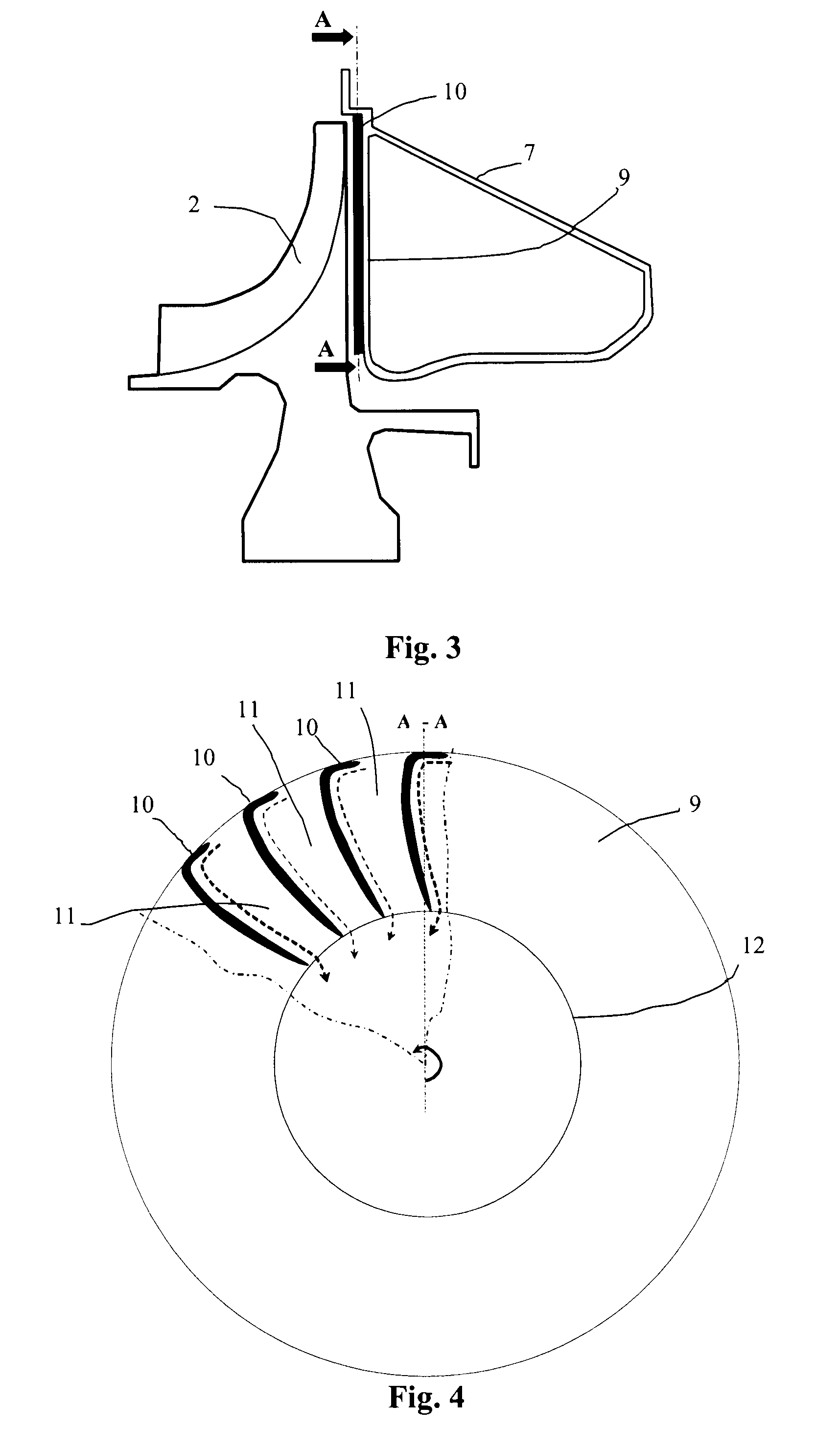
The present invention proposes a device to manage the pressure on the thrust bearing of a shaft bearing a centrifugal compressor. The device helps to increase the force of the thrust by controlling the circulation of air drawn off downstream of the compressor. The device avoids flow detachments and vortices at the level of the entry into the guide channels. The guide vane is oriented in a radial direction over the majority of its length, which eliminates the tangential component and optimizes the pressure on the downstream face of the centrifugal compressor without lowering the rate of the flow sent in the direction of the turbine.

Problems solved by technology

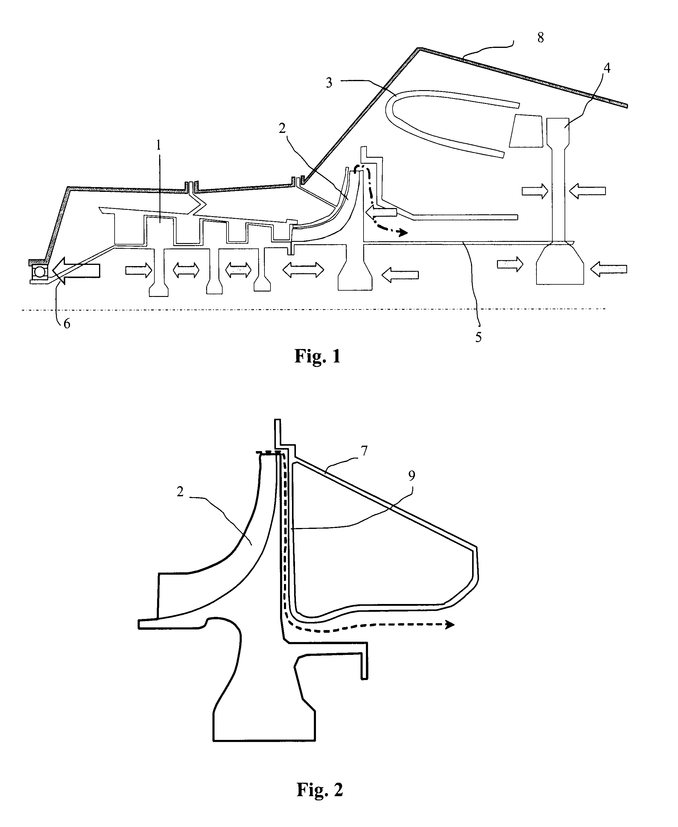
The presence of a tangential component for the velocity of the fluid, which is of no practical interest, has the drawback of reducing its static pressure and thus lessening the force applied to the downstream face of the centrifugal compressor.
The consequence of this is an axial thrust resultant oriented potentially rearwards, or at least oriented upstream but with insufficient support, which is contrary to the aspired aim to comply with the dimensioning specifications of the turbomachine.

Method used


Image

  • Control of axial thrust by guidance of the air drawn off from a centrifugal compressor
  • Control of axial thrust by guidance of the air drawn off from a centrifugal compressor
  • Control of axial thrust by guidance of the air drawn off from a centrifugal compressor

Examples


Embodiment Construction

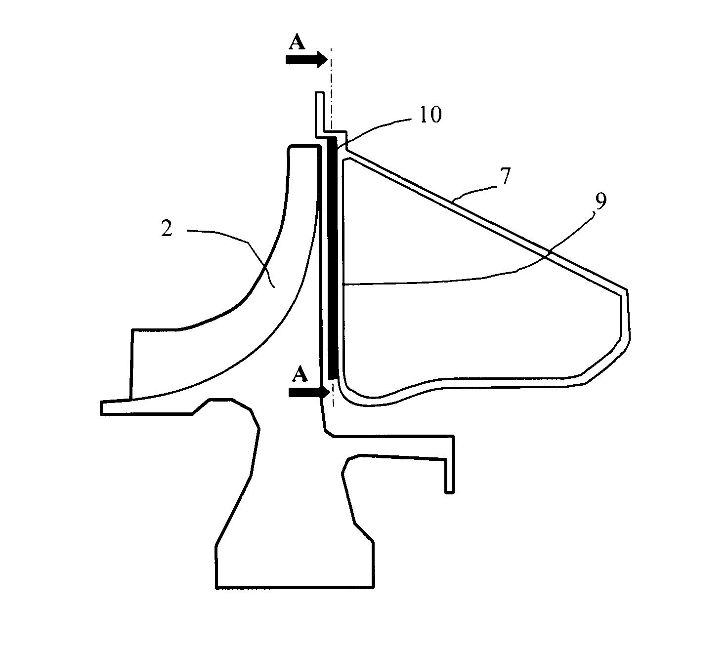
[0024]Referring to FIG. 1, the high-pressure body of a turbomachine comprising, in the direction of flow of the fluid, an axial compressor 1 followed, for the last compression stage, by a centrifugal compressor 2, is seen in schematic representation. Upon exit from this compressor, the compressed air passes via a guide vane (not represented) into a combustion chamber 3, where it is mixed with fuel and burnt to produce the power. The burnt gases pass through a high-pressure turbine 4, which draws off from them power to drive the compressors 1 and 2. The aggregate of compressors and turbine is mechanically connected by a high-pressure shaft 5, which is held in place in the turbomachine by means of, inter alia, a ball bearing 6 attached to the structure of the turbomachine. This bearing 6 forms a stop means for the shaft 5 and transmits the thrust forces resulting from the stresses exerted on the different parts of the high-pressure body. FIG. 1 shows, with the aid of grey-tinted arrow...


PUM


Abstract

An inner combustion chamber casing of a turbomachine, which is intended to be placed downstream of a centrifugal compressor, is provided. The casing has the shape of a disc, pierced by a central circle, and includes on its disc at least one guide vane of the drawn-off air. The guide vane extends longitudinally over the disc between the periphery of the disc and the central circle and spreads out axially from the disc so as to form with the downstream face of the centrifugal compressor a guide channel for the air which is drawn off upon exit from the said compressor. The guide vane has a curved shape orienting in a radial direction at the level of its most central end.

Description

BACKGROUND OF THE INVENTION[0001]1. Field of the Invention[0002]The field of the present invention is that of turbomachines and, more particularly, that of the calibration of the thrust exerted on the bearings of these turbomachines.[0003]2. Description of the Related Art[0004]A turbomachine is made up of numerous parts having, for the most part, transverse extensions in relation to its rotational axis, on which transverse extensions are exerted axial forces generated by the pressures of the air in which they bathe. The existing multiple cavities of pressurized air thus create stresses upon the turning parts (rotors) and upon the fixed parts (stators), which stresses add to the aerodynamic stresses exerted on the blades. Whereas the stresses incurred by the stators are sustained by the different casings, those experienced by the rotors add to these and their resultant is absorbed by the thrust bearing which supports the corresponding rotation shaft. It is necessary to control, for a...

Claims


Application Information

Patent Timeline
IPC IPC(8): F02C7/12F01D3/04F01D5/04F01D5/08F01D25/12F01D25/16F02C7/06F02C7/18F04D27/02F04D29/051
CPCF01D3/04F01D5/046F01D5/081F01D25/12F01D25/162F02C7/06F02C7/18F04D27/0207F04D29/051F05D2240/12F05D2260/20F04D29/0513F04D29/0516
Inventor BEHAGHEL, LAURENT DONATIENDALLAINE, FREDERICLEROUX, DELPHINEPEGOUET, BENJAMIN PHILIPPE PIERRE
Owner SN DETUDE & DE CONSTR DE MOTEURS DAVIATION S N E C M A
Why Eureka
Eureka Blog
Learn More