
Guide pin assembly for metal forming dies and method

a technology of metal forming dies and guide pins, which is applied in the direction of shaping tools, forging/pressing/hammering apparatuses, forging/hammering/pressing machines, etc., can solve the problems of large lead time, high cost of metal forming die design, manufacture, repair or modification, etc., and achieves economic manufacturing, adversely affecting the function of the guide pin assembly, and strong and durable during use

Active Publication Date: 2015-01-27
STANDARD LIFTERS INC
View PDF40 Cites 13 Cited by
  • Summary
  • Abstract
  • Description
  • Claims
  • Application Information

AI Technical Summary

Benefits of technology

The present invention is a guide pin assembly with the following technical effects: an uncomplicated construction that is strong and durable, secure locking function when assembled, can withstand high forces, requires no anti-rotation feature, can be easily assembled in a single pressing action, seamless appearance on the enlarged head portion of the guide pin assembly, allows for dampening under normal working conditions, and is well adapted for the proposed use.

Problems solved by technology

Current die making processes require carefully machined, precision holes and recesses in the die set for mounting the individual components, such that the same are quite labor intensive, and require substantial lead time to make, test and set up in a stamping press.
Consequently, such metal forming dies are very expensive to design, manufacture, and repair or modify.

Method used


Image

  • Guide pin assembly for metal forming dies and method
  • Guide pin assembly for metal forming dies and method
  • Guide pin assembly for metal forming dies and method

Examples


Embodiment Construction

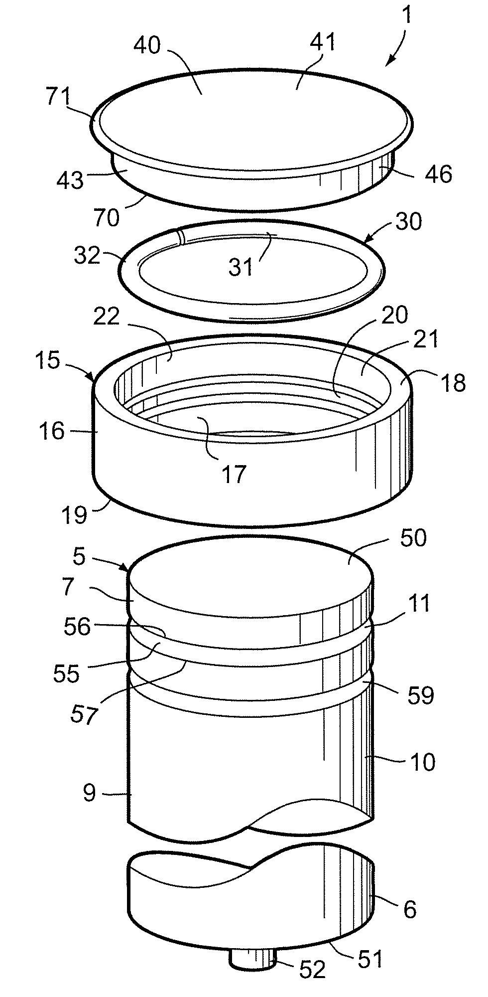
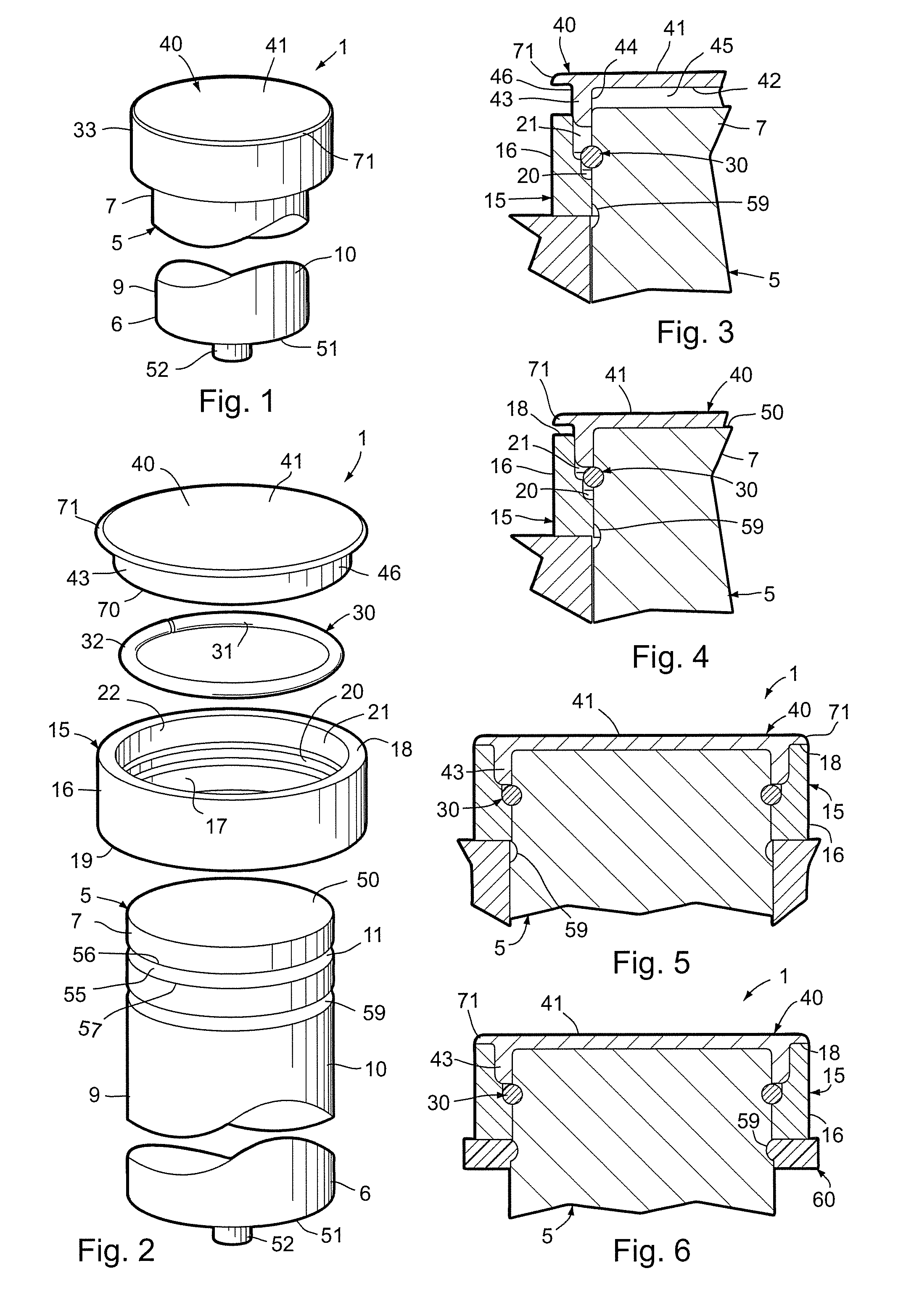
[0036]For purposes of description herein, the terms “upper,”“lower,”“right,”“left,”“rear,”“front,”“vertical,”“horizontal” and derivatives thereof shall relate to the invention as oriented in FIGS. 1 and 2. However, it is to be understood that the invention may assume various alternative orientations and step sequences, except where expressly specified to the contrary. It is also to be understood that the specific devices and processes illustrated in the attached drawings, and described in the following specification, are simply exemplary embodiments of the inventive concepts defined in the appended claims. Hence, specific dimensions and other physical characteristics relating to the embodiments disclosed herein are not to be considered as limiting, unless the claims expressly state otherwise.

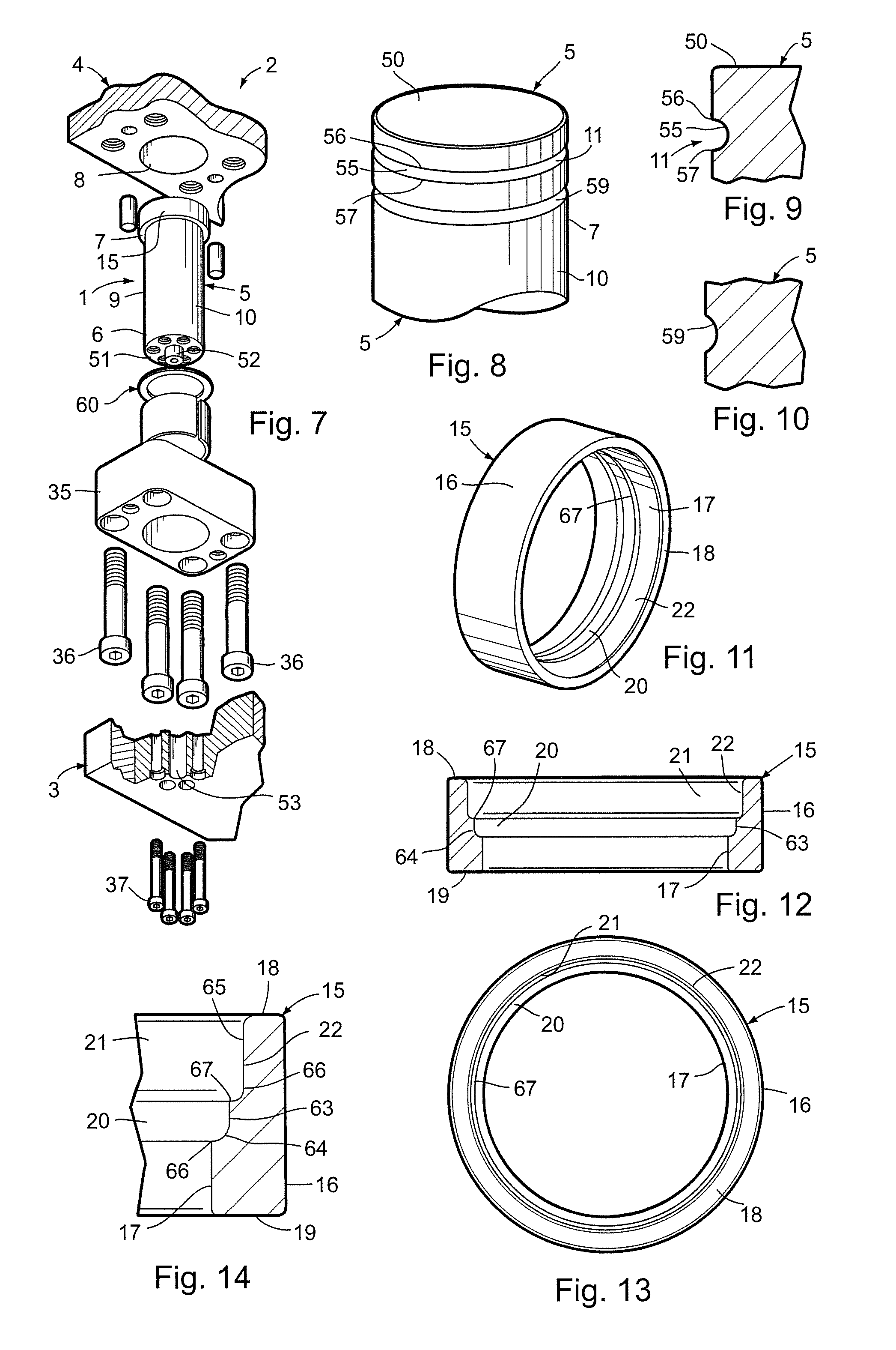
[0037]The reference numeral 1 (FIGS. 1-7) generally designates a guide pin assembly embodying the present invention, which is particularly adapted for use in conjunction with metal forming dies,...


PUM

PropertyMeasurementUnit
diameteraaaaaaaaaa
diameteraaaaaaaaaa
diameteraaaaaaaaaa

Abstract

A guide pin assembly for metal forming dies includes a cylindrical guide pin body with an external retainer groove adjacent one end thereof in which a retainer ring is received. An annular guide pin ring with an outside diameter greater than the pin body, has a counterbore adjacent the outside end thereof and a retainer groove in a medial portion thereof which receives the outer portion of the retainer ring to securely interconnect the pin body and the ring and thereby form an enlarged head at one end of the pin body which positively limits reciprocal motion between two associated die members. A circular guide pin head cap covers the outer end of the head ring, and includes a support collar that is closely received in the counterbore of the ring, and engages the retainer ring to securely hold the same in place.

Description

CLAIM OF PRIORITY[0001]The present application is related to commonly assigned, U.S. provisional patent application Ser. No. 61 / 611,135, filed Mar. 15, 2012, entitled GUIDE PIN ASSEMBLY FOR METAL FORMING DIES AND METHOD, which is incorporated herein by reference, and claims priority thereto under 35 U.S.C. §119.BACKGROUND OF THE INVENTION[0002]The present invention relates to metal forming dies and the like, and in particular to a guide pin assembly and associated method.[0003]Metal forming dies, such as stamping dies and the like, are well known in the art. Progressive metal forming dies are unique, very sophisticated mechanisms which have multiple stations or progressions that are aligned longitudinally, and are designed to perform a specified operation at each station in a predetermined sequence to create a finished metal part. Progressive stamping dies are capable of forming complex metal parts at very high speeds, so as to minimize manufacturing costs.[0004]Heretofore, the dies...

Claims


Application Information

Patent Timeline
Patent Type & Authority Patents(United States)
IPC IPC(8): B21D37/12B21D37/10
CPCB21D37/12Y10T29/49826Y10T29/49Y10T29/49876B21D37/10B21K1/76
Inventor BREEN, SCOTT M.PYPER, JOEL T.
Owner STANDARD LIFTERS INC
Learn More