
Navigating an interventional device

a technology of interventional devices and navigation devices, which is applied in the field of navigation interventional devices, can solve problems such as cluttering of interventional images, and achieve the effects of convenient interventional procedures, improved detection, and easy readable image information

Active Publication Date: 2015-01-27
KONINK PHILIPS ELECTRONICS NV
View PDF25 Cites 4 Cited by
  • Summary
  • Abstract
  • Description
  • Claims
  • Application Information

AI Technical Summary

Benefits of technology

[0004]Hence, there may be a need to provide enhanced information to the user, i.e. the operator, in an easily comprehensible manner.
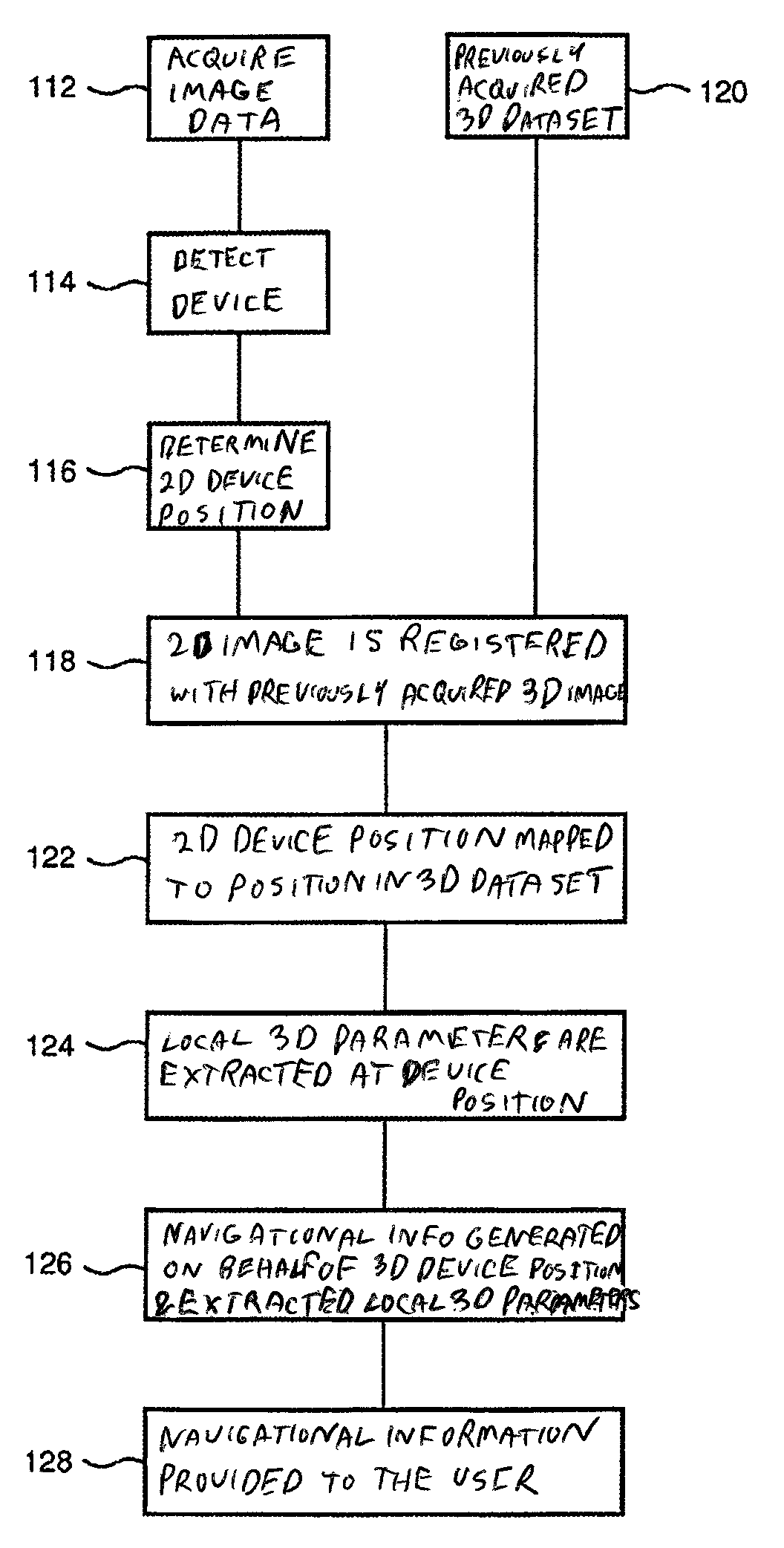
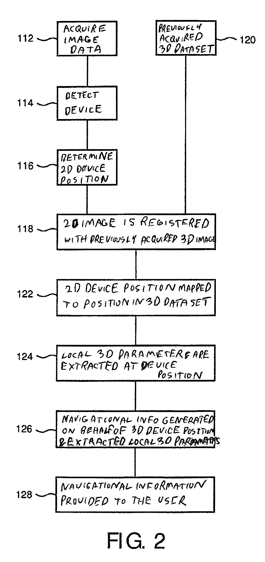
[0007]One of the advantages is that, although only one projection is provided for the X-ray fluoroscopy image, which one projection for itself does not provide any depth information, by mapping the determined two-dimensional position to a position in the 3D data set it is still possible to derive the necessary three-dimensional information as a basis for the navigational information being provided to the user. The navigational information can thus assist the user, for example a physician, to steer the device navigation, for example. By extracting local three-dimensional parameters, the interventional device serves as a pointer in the 3D data set or 3D volume. Since the two-dimensional information is acquired by two-dimensional X-ray fluoroscopy images, it is possible to continuously acquire such images in order to continuously track the two-dimensional device position and the related three-dimensional position during the navigation process, providing the possibility to communicate three-dimensional information to the physician, or the user, in real-time.
[0047]According to an exemplary embodiment of the invention, step e) comprises computing probabilities for different segments of the tubular structure; and maximizing accumulated probability from the different probabilities to determine in which segment of the tubular structure the device may be located. Further, on behalf of the accumulated probability information is gathered in space from the 3D dataset.
[0057]For example, when guiding a catheter or a wire tip through a vessel tree, it is important to get a good perception of the local vessel shape in three dimensions, in particular when confronted to strong out of plane bending or complex tortuosity. The usual three-dimensional road mapping technique provides a good projected road map in the X-ray fluoro plane, but is without depth information or at least less informative when it comes to the depth direction. When back-projecting the device into the 3D reconstructed vessel tree, the disadvantage is that this entails referring to a reconstructed and somewhat artificial viewing mode. Another serious problem is that three-dimensional data and two-dimensional projecting live views do not fuse very easily or naturally. By providing a very simple depth indication, such as an orientation vector, at the device location, this using of a device as a pointer to 3D data leads to a visualization that can easily be blended with the live image and does not clutter the fluoroscopy plane, which can thus stay as clear and unambiguous as possible. Another advantage is that, apart from the device tracking and registration steps already mentioned, one has simply to get orientation information from the three-dimensional data which does not require actual segmentation. This provides advantages concerning computational power and time required in the system.
[0066]Having an optimal view angle of the device which is being navigated through, for example, a vascular structure decreases the chance of misinterpretation on the side of the user due to a minimally foreshortened or even unforeshortened view in which no or at least only a minimum number of vessels overlap. For example, in case of a C-arm, the C-arm needs to be positioned manually by the operator for an optimal view. This requires full concentration and also experience by the user which has further disadvantages with respect to the duration of an interventional procedure. For example, the derived optimal viewing angle can be used to steer the C-arc of an X-ray system to the optimal viewing angle of the vessel segment pointed to by the device. This would then facilitate the interventional procedure, because the information to the user would be presented in an optimized way, i.e. better detectable and easier readable image information. This also means relieve for the user, since he or she can grasp the information in a shorter time, thus providing certain economical benefits.

Problems solved by technology

However, the projected roadmap is still a 2D “flat” representation of the vessels which does not provide depth information.
Additionally, overlaying the footprint of the vessels tends to clutter the interventional image, which should be left as clean as possible.

Method used


Image

  • Navigating an interventional device
  • Navigating an interventional device
  • Navigating an interventional device

Examples


Embodiment Construction

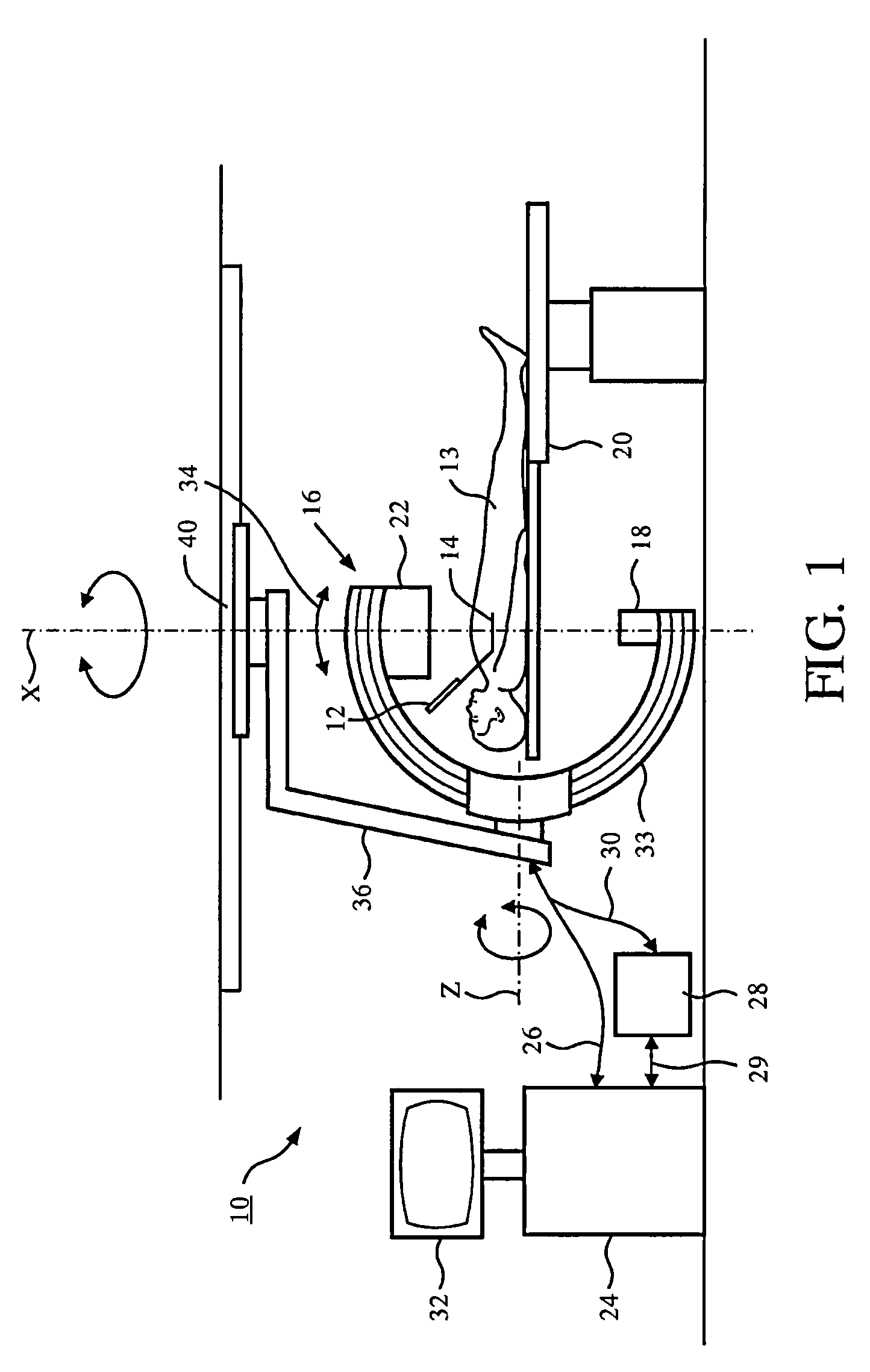
[0105]FIG. 1 schematically shows a system 10 for navigating an interventional device 12 within a tubular structure of an object, for example a patient 13. As an example, the interventional device is a guide-wire for percutaneous coronary interventions. The guide wire has a tip, indicated with reference number 14, but not further shown. The system 10 comprises an X-ray image acquisition device 16 with a source of X-ray radiation 18 provided to generate X-ray radiation. A table 20 is provided to receive a subject to be examined, for example the patient 13. Further, the X-ray image acquisition device 16 comprises a detection module 22 located opposite the source of X-ray radiation 18, i.e. during the radiation procedure, the subject or patient 13 is located between the source of X-ray radiation 18 and the detection module 22. The latter is sending data to a control unit or processing unit 24 connected to the X-ray image acquisition device 16 by a cable connection 26. Of course, the cab...


PUM


Abstract

The present invention relates to navigating an interventional device. In particular, the invention relates to a system for navigating an interventional device within a tubular structure of an object, a method for navigating an interventional device within a tubular structure of an object as well as a computer program element and a computer-readable medium. In order to provide enhanced information to the user in an easily comprehensible manner while keeping the X-ray dose to a minimum, a system and a method for navigating an interventional device within a tubular structure of an object are provided, wherein the method comprised the following steps: a) Acquiring 2D X-ray fluoroscopy image data in one projection geometry of a region of interest of the tubular structure; b) detecting the interventional device in the 2D X-ray image; c) determining the 2D position of the interventional device in the 2D X-ray image; d) registering the at least one 2D X-ray image with a previously acquired 3D dataset of the region of interest of the tubular structure; e) mapping the determined 2D position of the interventional device to a position in the 3D dataset; f) extracting local 3D parameters of the tubular structure at the position of the interventional device; g) generating navigational information on behalf of the determined 3D position of the interventional device and the extracted local 3D parameters; and h) providing the navigational information to the user.

Description

FIELD OF THE INVENTION[0001]The present invention relates to navigating an interventional device. In particular, the invention relates to a system for navigating an interventional device within a tubular structure of an object, a method for navigating an interventional device within a tubular structure of an object as well as a computer program element and a computer-readable medium.BACKGROUND OF THE INVENTION[0002]In order to use interventional devices in tubular structures where the location of the device is not visible to the user from the outside of the object, the user is provided with information about the location of the device in relation to the object. For example, during neurological interventions, devices are routinely used in the treatment process of diseased vessels. In order to assist the physician, for example a neurosurgeon, with navigating a specific device to the diseased vessel segment, the device and region of interest are visualized using X-ray imaging. For exam...

Claims


Application Information

Patent Timeline
Patent Type & Authority Patents(United States)
IPC IPC(8): G06K9/00A61B6/00G06T7/00G06T11/00
CPCG06T11/003G06T7/0024G06T11/008A61B6/52G06T2207/10072G06T2207/10121G06T2207/30101G06T2211/404G06T2211/428Y10S128/922G06T7/30
Inventor FLORENT, RAOULSCHOOENENBERG, GERT ANTONIUS FRANCISCUSVAN RENS, BRAM ANTONIUS PHILOMENA
Owner KONINK PHILIPS ELECTRONICS NV
Learn More