Devices and method for draw blow moulding a container and the corresponding use

a technology of blow molding and containers, applied in the field of devices for blow molding containers, can solve the problems of rotary motion, increase of the weight of the already high device, and not only of the enormous installation height of the blow molding device, so as to achieve the effect of cost-effective production and easy production

Active Publication Date: 2015-02-03
EUGEN SEITZ
View PDF5 Cites 6 Cited by
  • Summary
  • Abstract
  • Description
  • Claims
  • Application Information

AI Technical Summary

Benefits of technology

[0013]It is an object of the instant invention to overcome the disadvantages of the state of the art and to provide a device for blow molding a container from a parison, which is designed so as to be compact and which can be produced easily as well as cost-efficiently.
[0014]According to an embodiment, a connection is established between the blowing cylinder and a tubular electric linear motor, the armature of which is connected to the stretching rod and the stator of which is supported on the blowing cylinder. The blowing cylinder thereby represents that component, which docks to the bottle by means of performing a stroke, which is so far generated pneumatically and by means of which blowing air as well as the stretching rod are inserted into the bottle. The tubular electric motor combines all of the advantages of the state of the art, because it provides sufficient force, is cost-efficient and low-wear. On principle, such motors can be designed according to the Lorentz force principle as well as according to the Maxwell force principle. The difference to the flat or U-shaped linear motors is thereby that the exciter winding of the stator comprises the magnets in the rod-shaped armature in a circular (tubular) manner.

Problems solved by technology

The stretching rods are hereby often positioned by pneumatic cylinders and mostly in combination with a mechanical connecting rod, whereby the blow molding devices not only reach an enormous installation height, but also require a particularly stable design due to the parts, which are difficult to move as well as due to the forces appearing in the connecting rod due to the counteraction.
The already high weight of such a device is thus additionally increased and the rotary motion thereof, e.g., requires much energy in a blow molding machine.
Likewise, the energy consumption is very high due to the use of compressed air as drive medium.
A pneumatic / mechanic positioning of the stretching rods thus likewise increases the production and operating costs of a blow molding machine, which is designed in this manner.
Such linear motors provide for a highly accurate reproducibility when carrying out stretching motions, but encompass a comparatively high construction weight and a high price.
However, the fluid drives encompass disadvantages with reference to the positioning accuracy, in particular when carrying out positioning motions very quickly, because control processes can only be realized to a limited extent in consideration of the system inertias.
However, an important disadvantage of this combination lies in the fact that neither the weight nor the installation size of a blow molding machine can be decreased drastically, because an electric linear motor must also be integrated in addition to the fluid drive.
This solution furthermore still uses a fluid drive and thus a very expensive source of energy.
However, the advantage is here that only a large and heavy and thus very expensive linear motor, which is dimensioned accordingly, is able to provide the forces, which are typically provided by a fluid drive.
Despite all of the expected advantages, the machines provided with electric drives encompass deficiencies and have consequently never been realized.
A servo motor comprising spindle or belts, respectively, is thus extensive and expensive and displays considerable wear.
In turn, a linear motor as in European patent document EP 1 484 160 is flat, but also expensive and requires further components, such as linear guides, etc.
WO 2006 / 108380 is only used to regulate the travel and does not provide for the required force.

Method used


Image

  • Devices and method for draw blow moulding a container and the corresponding use
  • Devices and method for draw blow moulding a container and the corresponding use
  • Devices and method for draw blow moulding a container and the corresponding use

Examples


embodiment 10

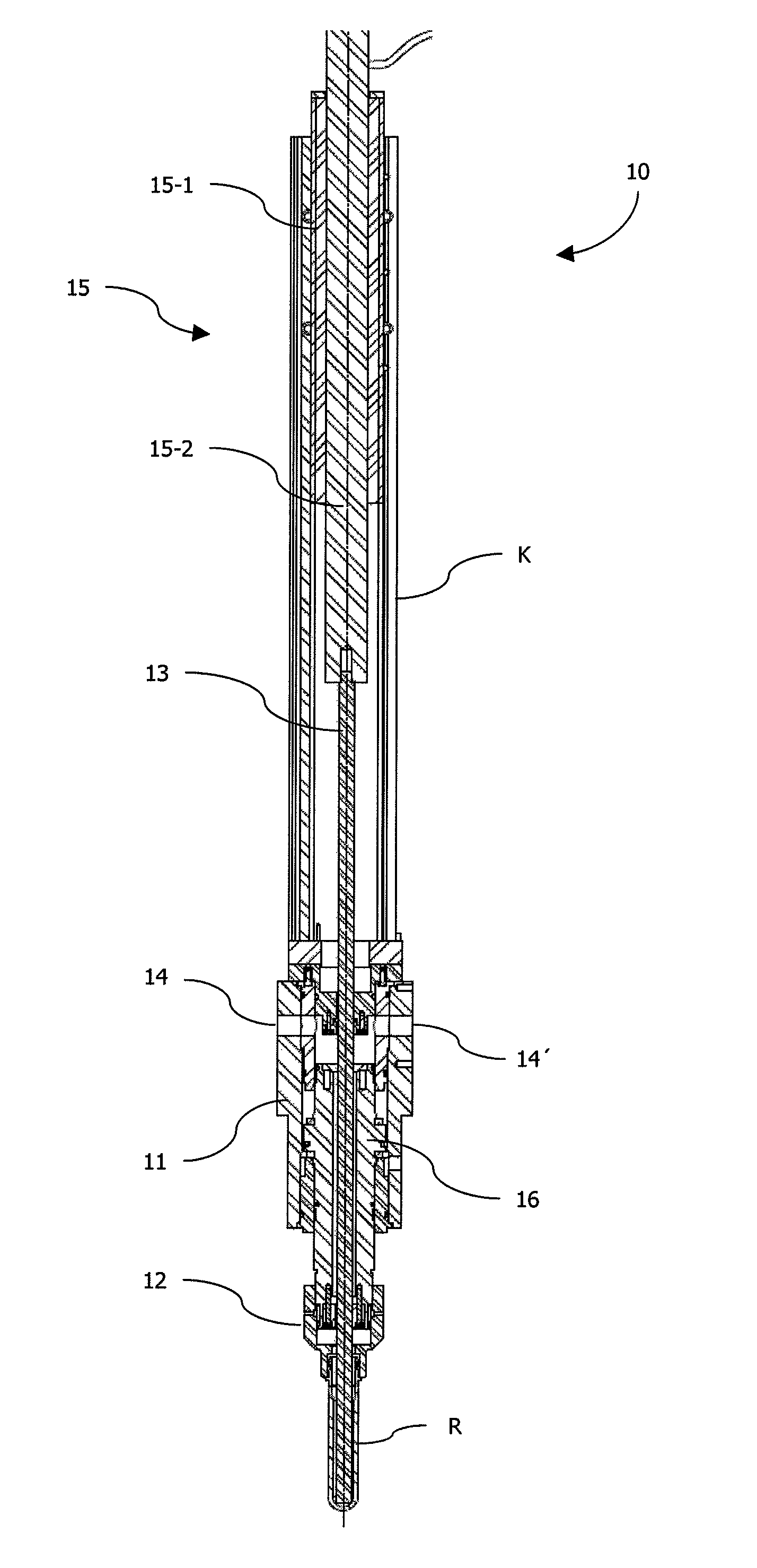
[0040]FIG. 1 shows a first compact embodiment 10 of a device according to the invention for blow molding containers from parisons R. The device 10 includes a blowing cylinder 11 and a blowing nozzle 12 mounted thereon, in which the parison R is accommodated. A stretching rod 13 can be passed through the nozzle 12 into the parison R and out of it again and is enclosed by the cylinder 11. Compressed air is supplied to the nozzle 12 via openings 14, 14′ in the cylinder 11, so as to blow up the parison R simultaneously or time-delayed to the stretching process against a hollow mold (not illustrated). The stretching rod 13 is driven via a tubular electric linear motor 15, the armature 15-2 of which is screwed to the stretching rod 13. Alternative connections, however, can also provide for a quick closure or a coupling. A quick replacement of the stretching rod 13 is thus possible as a function of the container production. The stator 15-1 of the motor 15 is accommodated in a housing, whic...

embodiment 20

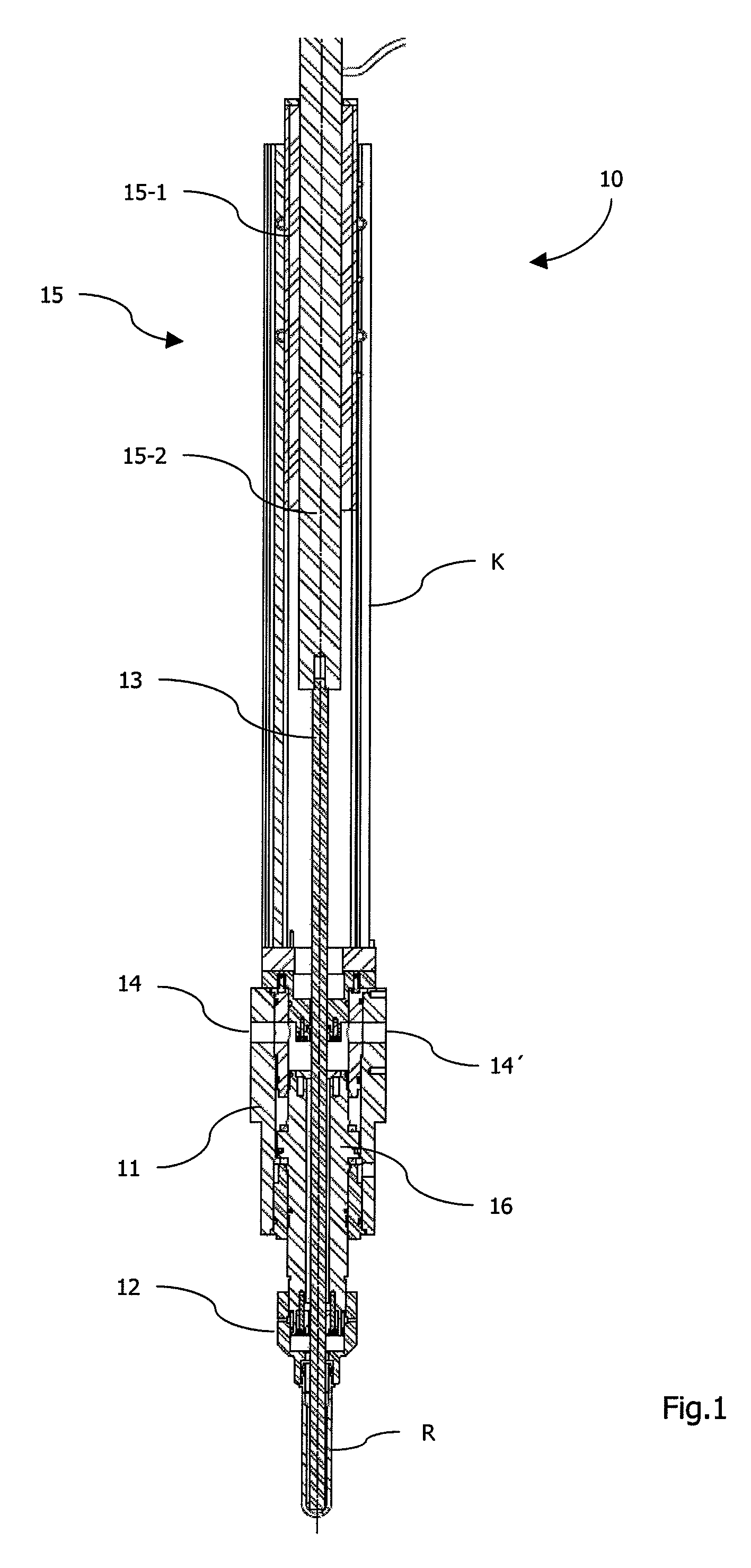
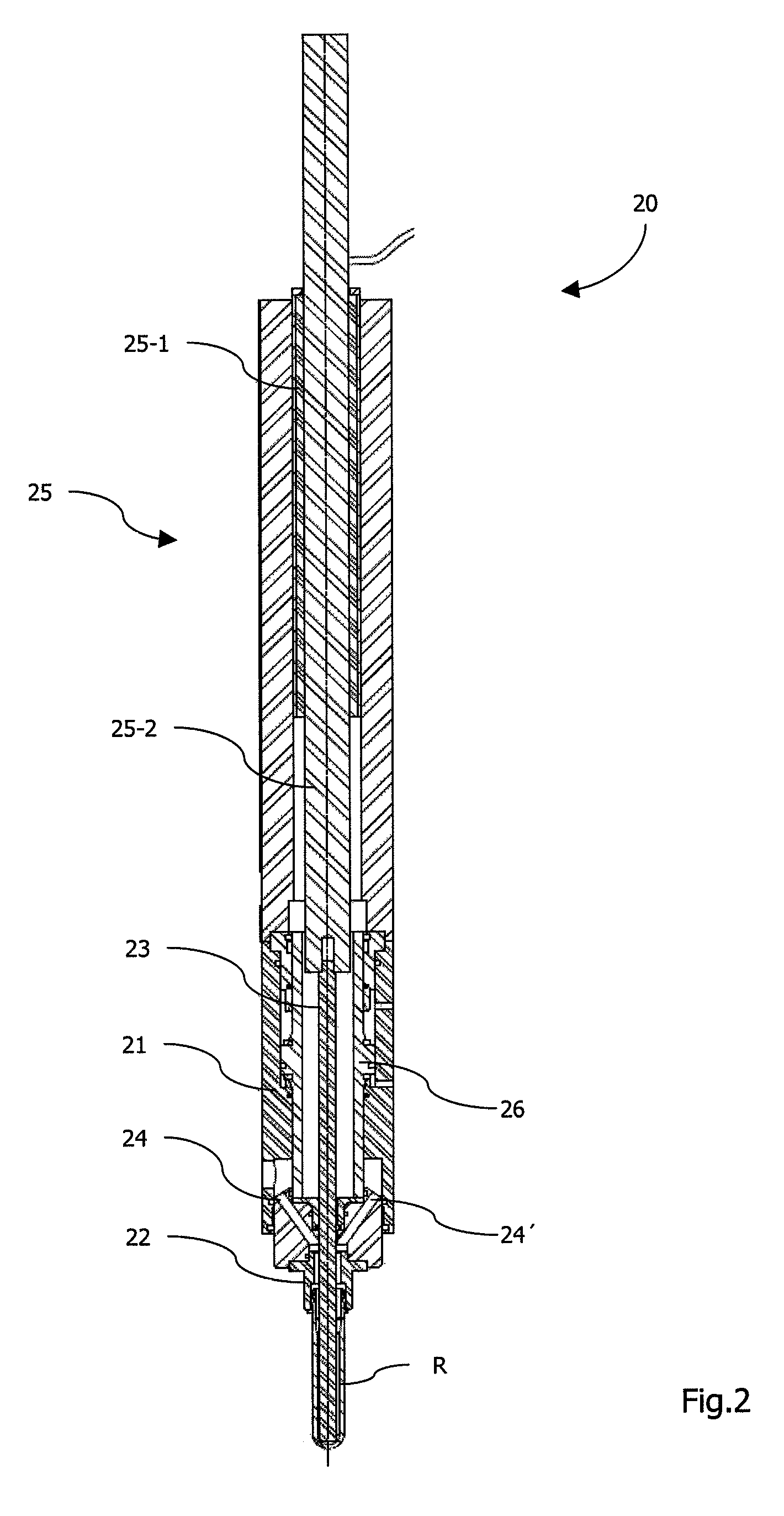
[0042]FIG. 2 shows a second, even more compact embodiment 20 of a device according to the invention. Contrary to the device 10 of FIG. 1, a blowing cylinder 21 as well as a blowing piston 26 supported therein is adapted to an armature 25-2 of a tubular electric linear motor 25 such that this armature 25-2 may be passed into the cylinder shortly in front of the parison R in one stroke movement (of approximately 400 mm). In the area of a free end, the piston 26 encompasses openings 24, 24′, which converge at right angles to a nozzle 22 mounted at this end and to which compressed air is supplied via corresponding openings in the cylinder 21. Compared to the device 10, this construction allows for a further shortening of the device 20 and reinforces the advantages already mentioned therein. As is already described in FIG. 1, a stretching rod 23 is thereby screwed to the armature 25-2 of the motor 25, so as to ensure a rapid replacement as a function of the container production. As a fun...

embodiment 40

[0044]FIG. 4 shows a fourth, even more compact embodiment 40 of a device according to the invention. A further shortening of the design thereof is attained in that the armature 45-2 of a tubular electric linear motor 45 is embodied as part of a stretching rod 43. A constructive adaptation of the entire head of the device as in FIGS. 2 and 3 is thus not necessary. A blowing cylinder 41 including openings 44, 44′, a blowing piston 46 and a blowing nozzle 42 can be removed from the device of FIG. 1 in an unchanged manner. The motor 45 including stator 45-1 can thus be arranged directly above the cylinder 41, because the motion of its armature 45-2, namely the stretching rod 43 herein, is not limited by the maximal depth of the cylinder 41.

[0045]Finally, FIG. 5 shows a fifth, even further compressed embodiment 50 of a device according to the invention. As is already shown in FIG. 4, the armature 55-2 of a tubular electric linear motor 55 is embodied as part of a stretching rod 53, thus ...


PUM

PropertyMeasurementUnit
stroke heightaaaaaaaaaa
heightaaaaaaaaaa
distanceaaaaaaaaaa

Abstract

The invention relates to a device (10) for blow molding a container from a parison, comprising a blowing cylinder (11) and a blowing nozzle (12) mounted thereon, in which the parison (R) can be fixed and with a stretching rod (13), enclose by the cylinder (11) and which may be passed through the nozzle (12), wherein the nozzle (12) can be supplied with compressed air via openings (14) in the cylinder (11). The station (10) is characterized in that the stretching rod (13) is driven by a single tubular electric linear motor (15) the stator (15-1) of which is mounted on the cylinder (11) and the armature (15-2) of which is connected to the stretching rod (13).

Description

CROSS-REFERENCE TO RELATED APPLICATIONS[0001]This application is a National Stage Application of PCT / CH2009 / 000357, filed Nov. 11, 2009, which designates the United States and claims the priority of European Patent Application No. 08405281.0, filed on Nov. 18, 2008.BACKGROUND[0002]1. Field of Invention[0003]The invention relates to a device for blow molding a container, as well as to the use of a tubular electric linear motor in such a device.[0004]2. Related Art[0005]Such blow molding devices are used, for example, in hollow stretch blow molding machines in the case of which a parison is stretch molded by the stretching rod within a blow mold in response to a thermal conditioning and is recast by the blowing pressure impact in the container. In the case of a container forming by means of the impact of blowing pressure, parisons made of a thermoplastic material, for example parisons made of PET (polyethylene terephthalate), are supplied to different processing stations within a blow...

Claims


Application Information

Patent Timeline
Patent Type & Authority Patents(United States)
IPC IPC(8): B29C49/00B29C49/06B29C49/12B29C49/42B29C49/48B29K67/00B29L31/00
CPCB29C49/12B29C49/4236B29C49/06B29C2049/1295B29C2049/4869B29K2067/00B29L2031/7158B29C49/1232B29C49/123B29C49/48185B29C49/42362B29C2949/0715
Inventor SCHMIDT, JOACHIM
Owner EUGEN SEITZ
Why Eureka
Try Eureka