Barcode reader with edge detection enhancement

a barcode reader and edge detection technology, applied in the field of processing analog scan data signals, can solve the problems of difficult to determine the exact, difficult and inability to produce analog scan data signals with precisely defined signal level transitions

Active Publication Date: 2015-02-10
HAND HELD PRODS +1
View PDF28 Cites 638 Cited by
  • Summary
  • Abstract
  • Description
  • Claims
  • Application Information

AI Technical Summary

Problems solved by technology

However, a result of such noise components or operating the scanner near the operational limits of the focal zones, the transitions from the first signal level to the second signal level and vice versa are not perfectly sharp, or instantaneous.
Consequently, it is sometimes difficult to determine the exact instant that each binary signal level transition occurs in the detected analog scan data signal.
As a practical matter, it is not possible in most instances to produce analog scan data signals with precisely-defined signal level transitions.
One drawback to these approaches is that thermal and “paper” (or substrate) noise imparted to the analog scan data input signal tends to generate “false” positive-going and negative-going transitions in the first derivative signal, and may also generate zero-crossings in the second-derivative signal.
Consequently, the circuit logic allows “false” first derivative peak signals and second-derivative zero-crossing signals to be passed on, thereby producing erroneous binary signal levels at the output stage of the signal processor.
This can result in significant errors during barcode symbol decoding operations, causing objects to be incorrectly identified and / or erroneous data to be entered into a host system.

Method used


Image

  • Barcode reader with edge detection enhancement
  • Barcode reader with edge detection enhancement
  • Barcode reader with edge detection enhancement

Examples


Embodiment Construction

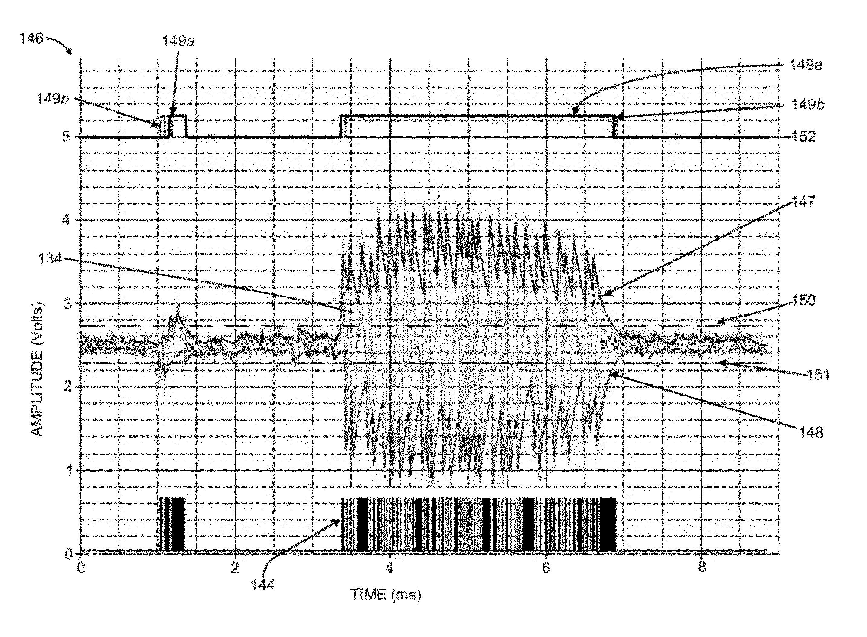
[0017]The present invention provides an apparatus and method for decoding optical indicia, such as barcodes, that more effectively distinguishes between actual barcode elements and signal noise. As will be explained in greater detail below, an optical reader or imager that is used to “read” an indicium will not always obtain a sharp representation of the barcode symbol due to optical, environmental, and physical factors. Common causes for a distorted signal include the barcode being at a position beyond the far depth of field limit (e.g., out of focus), the barcode may be poorly illuminated so the contrast between black and white is not distinct, or the signal includes paper or substrate noise. Substrate noise is present because the barcode substrate is usually paper, and the laser light is scattered off the fibers having a random spatial structure. Additionally, aperture is an important controlling factor in laser beam shaping. However, aperture truncation resulting from beam shapi...


PUM


Abstract

An optical reader for decoding an encoded symbol character of a symbology includes a scan data signal processor having as an input a scan data signal encoding information representative of the encoded symbol character. The scan data signal processor includes a first time delay stage adapted to provide a primary phase waveform from the scan data signal, a second time delay stage adapted to provide an early phase waveform from the scan data signal, and a third time delay stage adapted to provide a delayed phase waveform from the scan data signal. The early phase waveform has a propagation delay less than the primary phase waveform, and the delayed phase waveform has a propagation delay greater than the primary phase waveform. The scan data signal processor further includes a peak window detection stage for generating a peak window timeframe when an amplitude of the primary phase waveform is greater than, less than, or equal to both an amplitude of the early phase waveform and the delayed phase waveform. The optical reader further includes a digitizer circuit adapted to accept, within the peak window timeframe, the scan data signal processor output.

Description

FIELD OF THE INVENTION[0001]This disclosure relates generally to processing analog scan data signals generated from barcode symbol reading systems and, more specifically, to a circuit and method for enhanced barcode edge detection.BACKGROUND OF THE INVENTION[0002]Various optical scanning apparatus such as laser barcode scanners are widely used in diverse environments for purposes of object identification, data-entry and the like. The scanning apparatus have been developed to read and decode optical indicia, such as barcode symbols, that are attached, printed or otherwise fixed to the object to be identified. During operation of such apparatus, a focused light beam is produced from a light source such as a visible laser diode (VLD), and repeatedly scanned across the elements of the code symbol. In the case of barcode scanning applications, the elements of the code symbol consists of a series of bar and space elements of varying width. For discrimination purposes, the bars and spaces ...

Claims


Application Information

Patent Timeline
Patent Type & Authority Patents(United States)
IPC IPC(8): G06K9/38G06K7/10G06K7/14
CPCG06K7/10851G06K7/1452
Inventor GERMAINE, GENNADYXIAN, TAOFENG, CHENWANG, YNJIUNZHU, XIAOXUNCOLAVITO, STEPHENBLAKE, ROBERT
Owner HAND HELD PRODS
Why Eureka
Try Eureka