
Precoding matrix index selection process for a MIMO receiver based on a near-ML detection, and apparatus for doing the same

a mimo receiver and near-ml detection technology, applied in the field of wireless communication, can solve the problems of less advantageous techniques, limited interest, and selection criteria (c-sc) to achieve the effect of reducing the complexity of a mimo receiver

Inactive Publication Date: 2015-02-10
ST ERICSSON SA
View PDF5 Cites 3 Cited by
  • Summary
  • Abstract
  • Description
  • Claims
  • Application Information

AI Technical Summary

Benefits of technology

The present invention aims to provide a MIMO receiver that is simpler and more efficient than existing receivers. It incorporates a lattice reduction mechanism to significantly decrease the complexity of the receiver. Additionally, the invention provides an enhanced precoding index selection mechanism that can be used in a closed loop precoding technique of a MIMO communication system. This results in a more effective and efficient MIMO detection process.

Problems solved by technology

While the C-SC technique is the optimal in the case of the widely spread linear MMSE detector,—because of the maximization of the capacity which results—it should be noticed that such technique is less advantageous in the case of a more elaborated and sophisticated decoding technique, such as based on a non linear technique, such as achieved by a near-Maximum Likehood detection.
Indeed, thanks to its level of sophistication, a near-Maximum Likehood technique already achieves a high degree of capacity given a channel and, in such situation, the known Capacity-Selection Criterion (C-SC) index selection which is recommended by the 3GPP shows limited interest.

Method used


Image

  • Precoding matrix index selection process for a MIMO receiver based on a near-ML detection, and apparatus for doing the same
  • Precoding matrix index selection process for a MIMO receiver based on a near-ML detection, and apparatus for doing the same
  • Precoding matrix index selection process for a MIMO receiver based on a near-ML detection, and apparatus for doing the same

Examples


Embodiment Construction

[0044]The process which will be described hereinafter can be embodied in a wide number of applications. Clearly, any OFDM standard supporting MIMO spatial-multiplexing mode, e.g. IEEE 802.16, IEEE 802.11, 3GPP LTE and 3GPP LTE-A, can take advantage of the process described below.

[0045]More particularly, the invention is particularly advantageous in the case of a large number of antennas and consequently in the case of the 3GPP LTE-A standard.

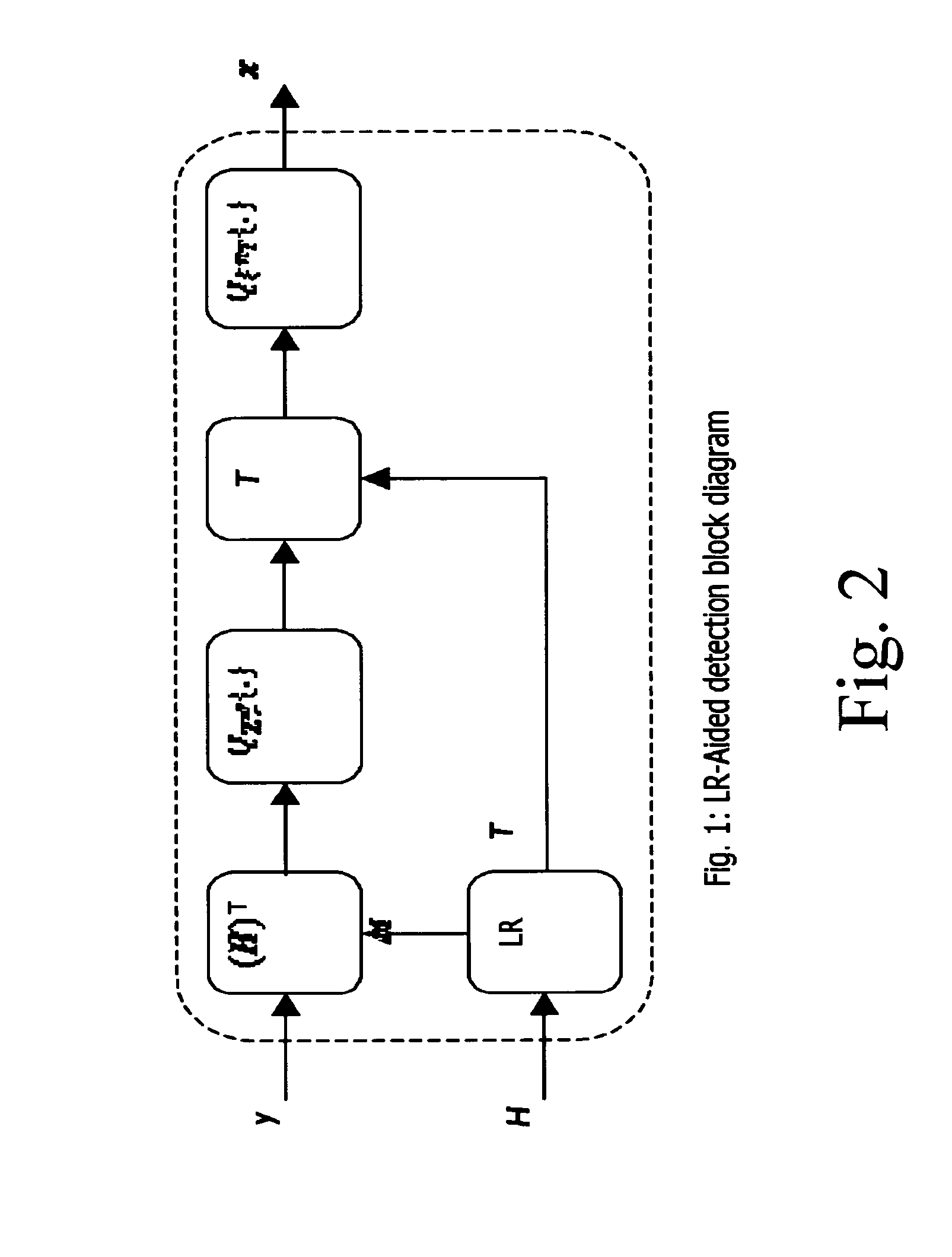
[0046]The process which will be described below with details is particularly useful for decreasing the complexity of a Lattice Reduction-Aided (LRA) detector which achieves high efficiency.

[0047]Indeed, it has been discovered by the inventors that Lattice Reduction-Aided (LRA) detection can be advantageously combined with a closed loop precoding technique, associated with one new Precoding Matrix Index (PMI) selection criterion having the effect of improving the conditioning of the channel matrix in the perspective of the LRA computation.

[0048]T...


PUM


Abstract

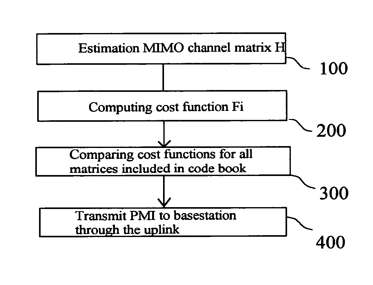
A process selects a Precoding Matrix Index (PMI) in a Multiple In Multiple Out (MIMO) receiver used in a wireless communications system including a base station communicating with User Equipments (UE) through a downlink and uplink channel. The base station applies a precoding on the transmit symbol vector based on a matrix selected from a set of predefined matrices and identified by a PMI index computed by the UE and forwarded to the base station via the uplink. The process includes estimating the MIMO channel matrix H of a given set of resources blocks comprising received symbol vectors, estimating the variance σ2 of the additive noise (AWGN), and computing for each particular matrix comprised within the set of predefined matrices a cost function representative of the orthogonality of the matrix MIMO channel matrix H. The process further includes comparing the values of the cost function and transmitting to the base station the index corresponding to the matrix corresponding to the best conditioned MIMO channel matrix according to the comparison of the values.

Description

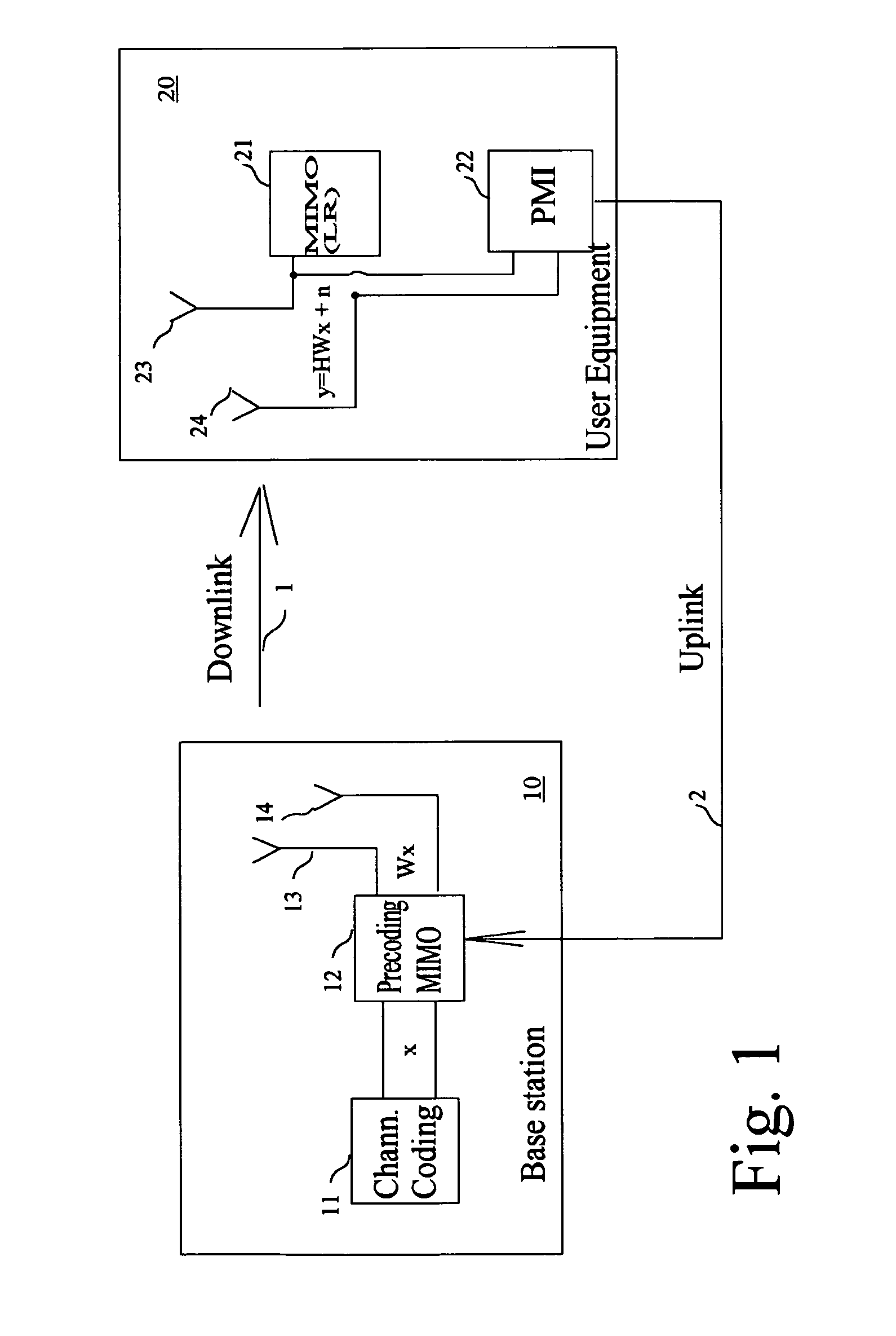
TECHNICAL FIELD[0001]The invention relates to the field of wireless communications and more particularly to a process for performing the selection of a Precoding Matrix Index (PMI) for a MIMO receiver using near-ML detection, such as Lattice Reduction Aided (LRA) mechanism, and a receiver for doing the same.BACKGROUND ART[0002]Spatial multiplexing is a common scheme for Multiple-In-Multiple-Out (MIMO) communication systems lying on the transmission over different antennas of independent information streams.[0003]Spatial multiplexing is conventionally combined with precoding which improves the ergodic capacity of the resulting transmission channel. FIG. 1 particularly illustrates the example of a 2×2 MIMO communication—composed of a downlink 1 and an uplink 2—between a base station 10 and a mobile equipment, such as an User Equipment.[0004]Considering base station 10, the latter includes a channel coding block 11 providing two independent data streams to a MIMO Precoder 12 which appl...

Claims


Application Information

Patent Timeline
Patent Type & Authority Patents(United States)
IPC IPC(8): H04B7/02H04B7/04H04B7/06
CPCH04B7/0456H04B7/0452H04B7/0639H04B7/0697
Inventor AUBERT, SEBASTIENANCORA, ANDREA
Owner ST ERICSSON SA
Learn More