Exhaust gas recirculation device

a technology of exhaust gas and recirculation device, which is applied in the direction of mechanical equipment, machines/engines, electric control, etc., can solve the problems of difficult to contain exhaust gas in the intake air, and achieve the effects of suppressing emission, suppressing heat exchanger corrosion, and reducing adverse influence of exhaust gas

Inactive Publication Date: 2015-02-17
TOYOTA JIDOSHA KK
View PDF9 Cites 4 Cited by
  • Summary
  • Abstract
  • Description
  • Claims
  • Application Information

AI Technical Summary

Benefits of technology

[0011]According to the present invention, the heat exchanger is disposed nearer the other end of the EGR passage than the on-off valve, and therefore, the high-density exhaust gas after passing the heat exchanger and being cooled can be temporarily held between the EGR control valve and the on-off valve. Consequently, when the internal combustion engine is started again, the exhaust gas temporarily reserved in the EGR passage can be introduced to the combustion chamber, thereby further suppressing the emission. Additionally, the inside of the heat exchanger can be kept in a state continuously communicating with the exhaust passage even if the on-off valve is closed, thereby reducing an adverse influence on the exhaust gas caused by the condensation of steam in the exhaust gas, so as to suppress the corrosion of the heat exchanger from advancing as possibly as in the conventional exhaust gas recirculation system without an on-off valve.
[0012]In the case where the volume of the EGR passage between the EGR control valve and the on-off valve corresponds to the displacement of the internal combustion engine, it is possible to contain the exhaust gas temporarily reserved in the EGR passage in the intake air to be supplied to each of the cylinders together with the fuel when the internal combustion engine is started again. As a consequence, the emission can be more securely reduced.
[0013]In the case where the exhaust gas recirculation system further includes the means for increasing the pressure of the exhaust gas introduced to the EGR passage, the pressure of the exhaust gas temporarily reserved in the EGR passage between the EGR control valve and the on-off valve can be readily increased. Consequently, it is possible to more accurately perform the EGR control when the internal combustion engine is started again.

Problems solved by technology

However, there is no effective exhaust gas at the EGR passage when the internal combustion engine is started again during the idle stopping control, and therefore, it is difficult to contain the exhaust gas in the intake air that is supplied to the combustion chamber together with the fuel at the beginning of the start.

Method used


Image

  • Exhaust gas recirculation device
  • Exhaust gas recirculation device
  • Exhaust gas recirculation device

Examples


Embodiment Construction

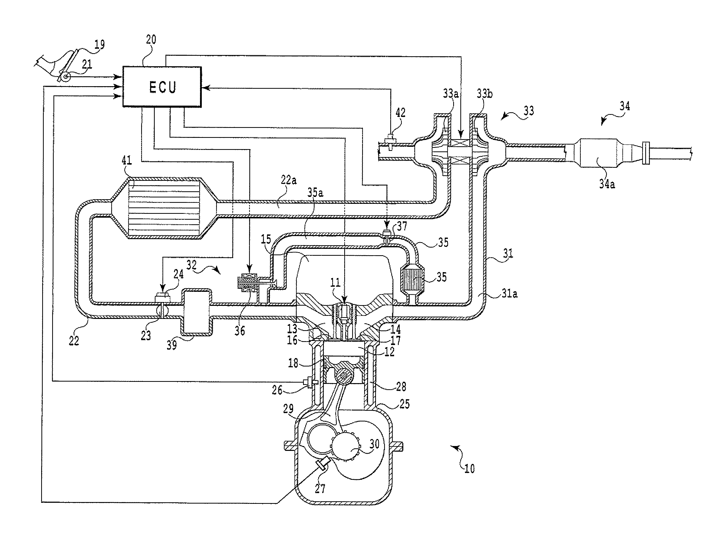
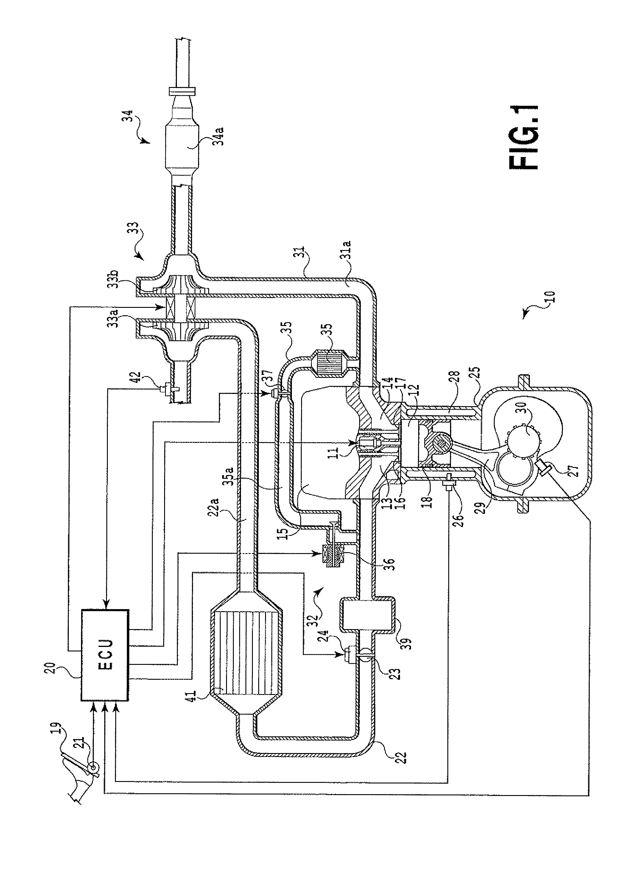
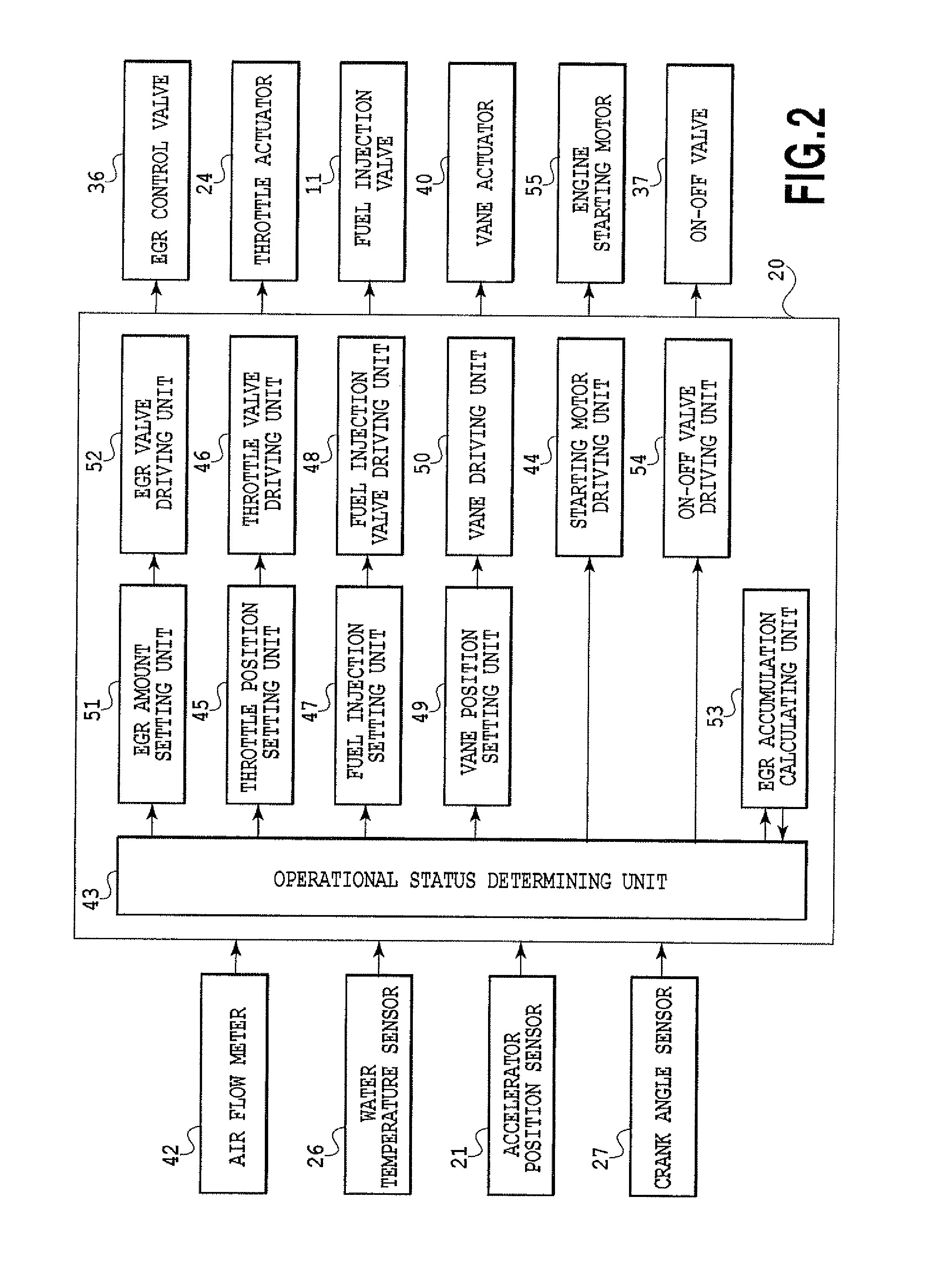
[0017]An embodiment in which an exhaust gas recirculation system according to the present invention is applied to a compression ignition type internal combustion engine will be explained in detail with reference to FIGS. 1-3. However, the present invention is not limited to the embodiment and the construction thereof may be freely modified according to characteristics required for targets to which the present invention can be applied. The present invention is effectively applied to, for example, a spark ignition type internal combustion engine in which gasoline, alcohol, LNG (Liquefied Natural Gas), or the like is used as fuel to be ignited by a spark plug.

[0018]FIG. 1 illustrates the conception of an engine system in the present embodiment, and FIG. 2 illustrates a control block in the engine system. Specifically, an engine 10 in the present embodiment is a compression ignition type multi-cylinder internal combustion engine in which light oil as fuel is directly injected into a com...


PUM


Abstract

An exhaust gas recirculation system according to the present invention includes an EGR passage for introducing a part of exhaust gas emitted from an engine to an intake passage, the EGR passage communicating at one end thereof with the intake passage whereas at the other end thereof with an exhaust passage, an EGR control valve for controlling the flow rate of the exhaust gas flowing therein, the EGR control valve being disposed at one end of the EGR passage, an on-off valve for opening or closing the EGR passage, the on-off valve being disposed at the other end of the EGR passage, and a heat exchanger for cooling the exhaust gas introduced to the EGR passage, the heat exchanger) being disposed nearer the other end of the EGR passage than the on-off valve.

Description

TECHNICAL FIELD[0001]The present invention relates to an exhaust gas recirculation system capable of adding a part of exhaust gas to intake air so as to suppress the production amount of emission, that is, nitrogen oxide.BACKGROUND ART[0002]There has been known an EGR (Exhaust Gas Recirculation) system that returns a part of exhaust gas flowing in an exhaust passage to a combustion chamber through an intake passage, and then, decreases the combustion temperature of an air-fuel mixture staying inside of the combustion chamber, so as to reduce the ratio of nitrogen oxide to the exhaust gas. In this EGR system, an EGR control valve capable of opening or closing an EGR passage is interposed in the EGR passage communicating with the intake passage and the exhaust passage at both ends thereof, thereby recirculating the exhaust gas toward the intake passage in a predetermined operational region.[0003]In recent years, a social demand for purification of exhaust gas has been remarkably escal...

Claims


Application Information

Patent Timeline
Patent Type & Authority Patents(United States)
IPC IPC(8): F02M25/07F02B29/04F02D41/00F02D41/04
CPCF02M25/0726F02M25/0724F02M25/0727F02M25/0731F02D41/042F02M25/0743F02M25/0745F02D41/005Y02T10/121F02B29/0406F02M25/0707F02D41/0077F02M26/39F02M26/05F02M26/21F02M26/22F02M26/23F02M26/28F02M26/37Y02T10/40Y02T10/12
Inventor TAKAMIYA, FUMIO
Owner TOYOTA JIDOSHA KK
Why Eureka
Try Eureka