Energy-deposition systems, equipment and method for modifying and controlling shock waves and supersonic flow

a technology of energy-deposition system and supersonic fluid flow, which is applied in the direction of continuous jet plants, machines/engines, instruments, etc., can solve the problems of not meeting all of the constraints on mass, designers cannot cover the inlet again while in flight to evacuate the region, and it is impossible to achieve the effect of reducing the risk of abrasion

a technology of energy-deposition system and supersonic fluid flow, which is applied in the direction of continuous jet plants, machines/engines, instruments, etc., can solve the problems of not meeting all of the constraints on mass, designers cannot cover the inlet again while in flight to evacuate the region, and it is impossible to achieve the effect of reducing the risk of abrasion

US8960596B2Active Publication Date: 2015-02-24KREMEYER KEVIN

Image

  • Energy-deposition systems, equipment and method for modifying and controlling shock waves and supersonic flow
  • Energy-deposition systems, equipment and method for modifying and controlling shock waves and supersonic flow
  • Energy-deposition systems, equipment and method for modifying and controlling shock waves and supersonic flow

Examples


examples

[0110]The following examples are given as particular embodiments of the invention and to demonstrate the advantages thereof It is understood that the examples are given by way of illustration and are not intended to limit the specification or the claims that follow in any manner.

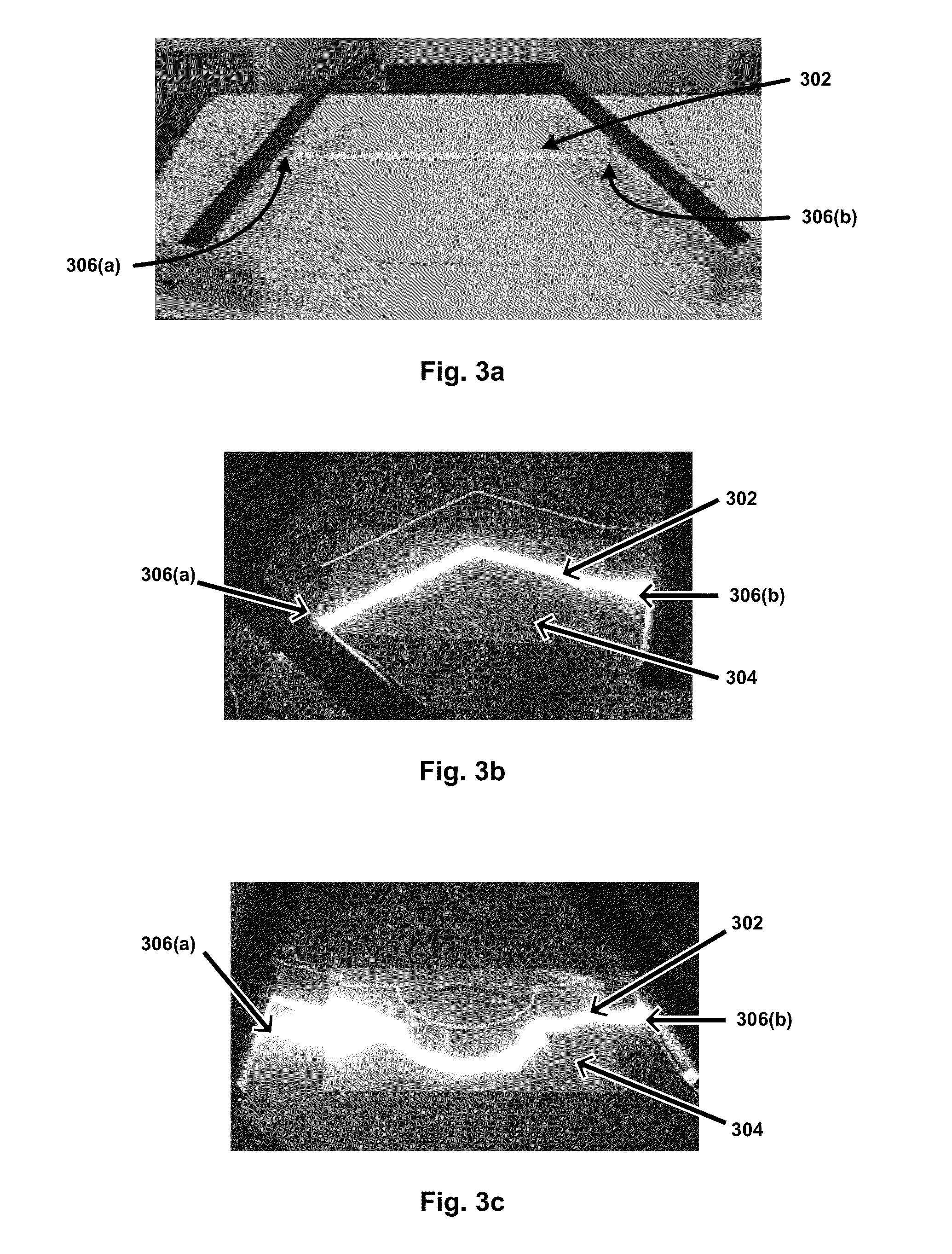
[0111]As is illustrated in FIGS. 3(a)-(c), experiments were performed wherein conductive graphite paths (302) were formed on paper surfaces (304) in various geometric patterns, such as a straight-line conductive path (see FIG. 3(a)), a sharp angle conductive path (see FIG. 3(b)), and a semi-circular conductive path (see FIG. 3(c)). The conductive paths were formed such that they did not change the mechanical smoothness or flow properties across or along the surface. All such conductive paths were then connected to electrodes (306a and 306b) on each end, and sufficient voltage and charge was applied to the conductive paths from the electrodes to cause energy deposition along the conductive paths by electric a...


PUM


Abstract

Systems, equipment, and methods to deposit energy to modify and control shock waves and hypersonic or supersonic fluid flow, including systems for controlling, mitigating, and / or effecting air flow in relation to air vehicles, wind tunnels, or other assets, or the like, as well as systems, equipment, and methods for disrupting the shock structure at the inlet for the engine of an air vehicle traveling at supersonic or hypersonic speed; mitigating blast effects on vehicles; mitigating heating of throats in supersonic and hypersonic wind tunnels, as well as control the flow parameters and Mach number in their test sections.

Description

CROSS REFERENCE TO RELATED APPLICATION[0001]This application is the National Phase application of International Application No. PCT / US2008 / 009885, filed Aug. 20, 2008, which designates the United States and was published in English, and which further claims the benefit of priority from U.S. Provisional Application No. 60 / 935,580, filed on August 20, 2007. The foregoing related applications, in their entirety, are incorporated herein by reference.INCORPORATION BY REFERENCE[0002]The present application further incorporates herein by reference the contents, in their entirety, of U.S. patent application Ser. No. 11 / 540,964, filed on Oct. 2, 2006, and U.S. patent application Ser. No. 11 / 288,425, filed on Nov. 29, 2005, as well as U.S. Pat. No. 7,121,511, U.S. Pat. No. 7,063,288 and U.S. Pat. No. 6,527,221.FIELD OF THE INVENTION[0003]This invention relates to systems, equipment, and methods to deposit energy to modify and control shock waves and hypersonic or supersonic fluid flow. The in...

Claims


Application Information

Patent Timeline
24 Feb 2015
Publication
US8960596B2
IPC
F02K7/14; G01M9/06
CPC
F02K7/14; G01M9/065; F05D2250/51; Y10T137/0536; Y02T50/60; F15D1/008; F15D1/12
Inventors
KREMEYER, KEVIN