Vertical axis wind turbine with axial flow rotor

a technology of axial flow and wind turbine, which is applied in the direction of motors, climate sustainability, sustainable buildings, etc., can solve the problems of increasing urgency, and affecting the power supply of wind turbines. achieve the effect of optimizing power extraction

Inactive Publication Date: 2015-02-24
WOLFF JOHN GEORGE
View PDF5 Cites 26 Cited by
  • Summary
  • Abstract
  • Description
  • Claims
  • Application Information

AI Technical Summary

Benefits of technology

[0032]A “stator assembly” mounted over the entry base of the turbine rotor swept area intercepts portions of the swirling airstream and redirects the air flow vertically as boundary layers of high intensity laminar flow along the stator surfaces. Stationary vanes extend at angles relative to the axis of rotation, intersecting the turbine blade leading edges during the rotational cycle, beginning at the blade tip and progressing to the root. The trailing edge of each vane is positioned in optimal proximity to the leading edges of turbine blades, such that the turbine blades may rotate freely without contact with the vanes yet close enough to receive high velocity air flow selectively in a predetermined manner so as to optimize power extraction over a variety of wind conditions. Vanes may be curved to extend the period of intersection in a predetermined manner.

Problems solved by technology

Rapidly increasing cost of energy and shrinking supply of conventional carbon fuels increases the urgency to improve wind power technology.
Yet despite their technical superiority, HAWT have fallen from grace among many people in recent times. Its detractors claim HAWT have serious drawbacks in that they pose great peril to many avian species due to the location along migration routes and large diameter of the swept area of the turbine blades.
Located near residential areas, the turbines are attributed to cause health problems in humans due to low frequency sound waves emanating from the exposed blades.
On the operational side, some researchers claim serious drawbacks in HAWT wind farms, where multiple turbines require large distance separation in order to avoid the “wake” effects of turbulence from adjacent turbines, thereby reducing wind energy availability.
Wind farms must be located in remote areas, requiring costly electrical grids to transport electrical capacity to populated areas.
VAWT technology has unrealized potential worthy of exploration.
Part of the energy is thereby lost or unavailable for extraction by the turbine, which makes the cross-wind turbine a less efficient mechanism overall.
Such efforts at times lead to intricate, costly designs requiring highly specialized tooling and fabrication techniques that present challenges to production for widespread distribution of the devices.
In the case of omni-directional devices in this class, a possible inefficiency comes from air circumventing the swept area of the turbine rotor and consequent loss of a portion of the available power to drive the fan.
Axial flow type rotors which rely on secondary airflow redirected via diverters or through venturi openings lose considerable portion of available power when the secondary airflow is dispersed over the swept area of the turbine rotor.
None of the developments in the prior art disclose or contemplate augmented or modulated power extraction by means of stationary vanes aligned over the inbound face of the swept area of an axial-flow turbine rotor so as to focus high intensity air streams upon the leading edges of blades in a continuous progression to optimize energy extraction from ambient wind over a variety of wind conditions.
Positioning the rotor so as to receive airflow laterally would defeat the intent of the horizontal axis wind turbine and produce results of questionable value.

Method used


Image

  • Vertical axis wind turbine with axial flow rotor
  • Vertical axis wind turbine with axial flow rotor
  • Vertical axis wind turbine with axial flow rotor

Examples


embodiment 10

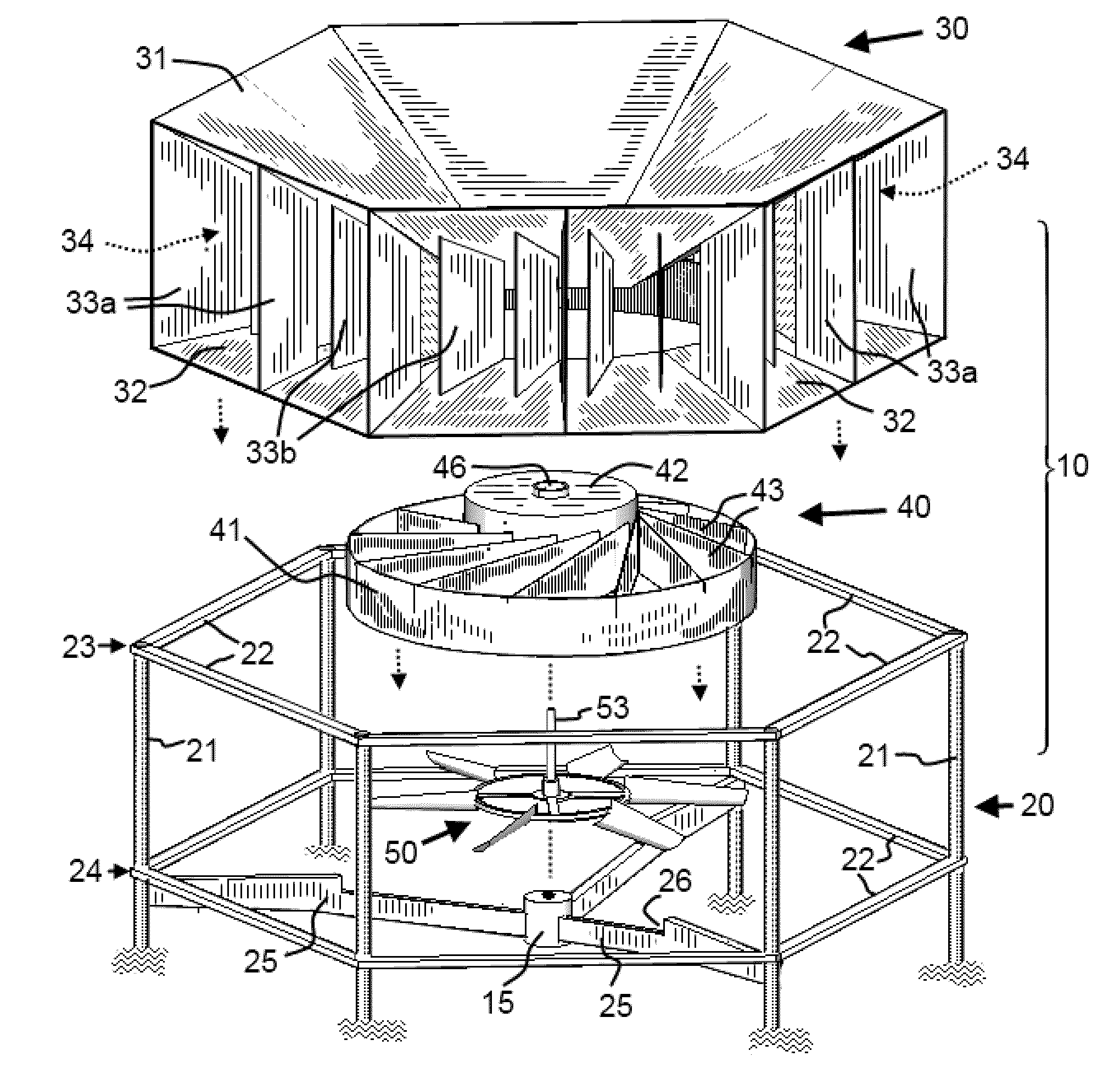
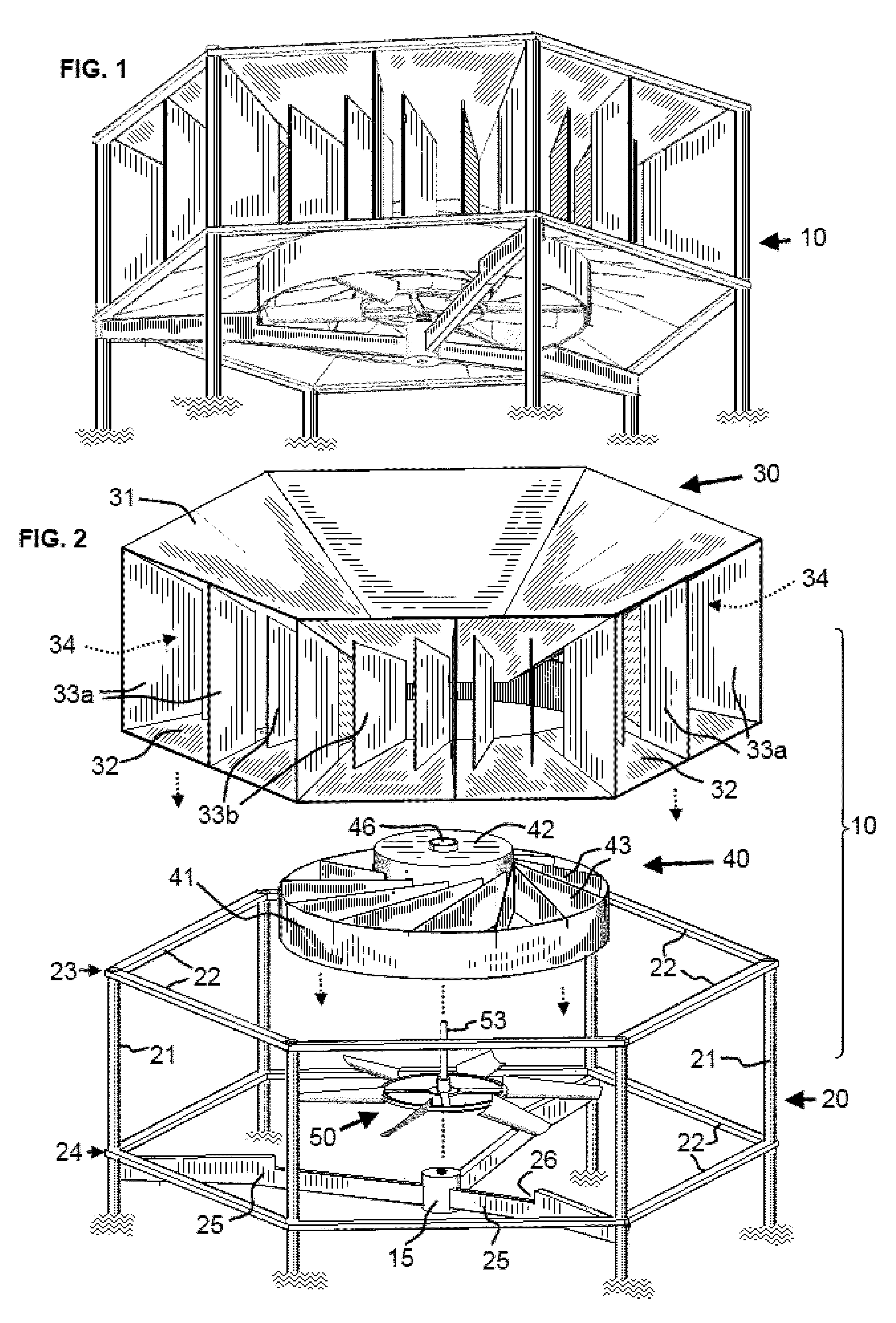
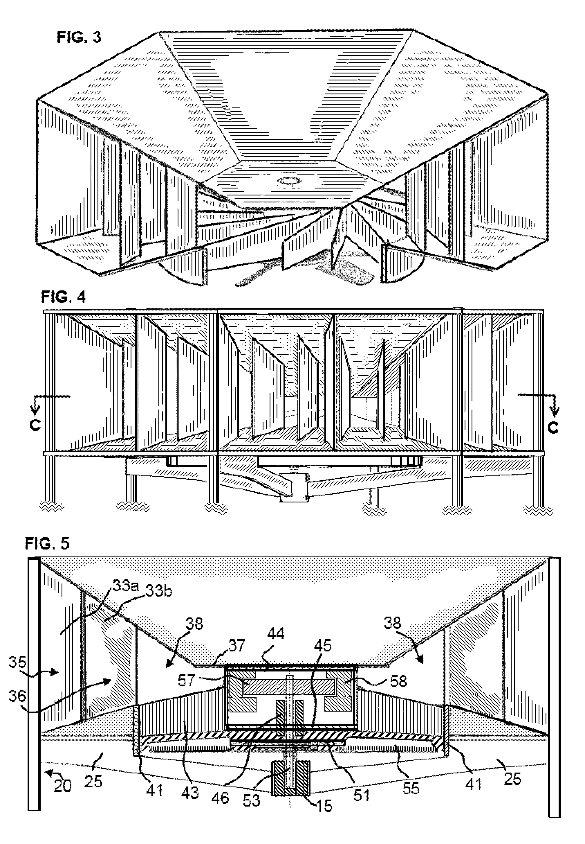
[0052]In the drawings, FIG. 1 through FIG. 5 illustrate an embodiment 10 of the vertical axis turbine of this invention, in which air flows through the turbine rotor in a downwardly direction and is expelled at the base.

[0053]FIG. 2 illustrates embodiment 10 in an exploded view for greater clarity. The vertical axis turbine is mounted within a tower structure 20 for placement on or above a surface such as a field or building rooftop. A collector assembly 30 intercepts and captures wind flowing across the outer facade of the turbine. A stator assembly 40 redirects the incoming wind flow vertically, and an axial flow turbine rotor 50 intercepts the vertical airflow to rotate the rotor.

[0054]Tower Structure

[0055]Vertical frame members 21, which may be steel posts or other suitable structural components, are interconnected by means of horizontally aligned struts 22, to form a rigid tower structure 20 to be anchored on some surface, for supporting the turbine assembly. The vertical frame...

embodiment 11

[0084]In embodiment 11 the collector assembly 30A intercepts and captures wind flow blowing across the outer sides of the turbine, the stator assembly 40A redirects the incoming wind flow upwardly, and an axial flow turbine rotor 50A intercepts the upward airflow to rotate the rotor.

[0085]Operation

[0086]The operation of the turbine may be described with reference to FIGS. 6, 7, 8, 9, 10, 11A, 11B, 11C, and 110 which illustrate various operational features schematically.

[0087]In reference to FIG. 6, 7, 8 and FIG. 10, ambient wind, illustrated by directional arrows 73, flowing in the direction of the turbine is intercepted or “captured” by the collector passages 35 positioned facing wind direction. Airflow is directed inwardly by the first set of vertical panel members 33a, and is redirected into a swirling stream on the inlet side of the turbine rotor by the second set of vertical panel members 33b. The second vertical panel members 33b are positioned at angles relative to the radial...


PUM


Abstract

An omni-directional vertical axis wind turbine includes an axial flow turbine rotor to supply force to operate an electrical generator mounted for rotation on a vertical shaft. A shroud surrounds the turbine rotor forming a circular chamber coaxially with the turbine rotor, enclosing the airflow entry face and leaving the discharge face uncovered. Wind entering the shroud from any direction flows inwardly through air passages, where a set of baffles surrounding the circular chamber redirect incoming airflow into a stream within the circular chamber. A cylindrical enclosure mounted concentrically with the turbine rotor within the circulation chamber houses an array of stationary vanes positioned to extend across the entry base and in close proximity to the turbine rotor and aligned at angles relative to the axis of rotation, form flow-through passages to intercept the airflow and redirect it vertically into the swept area of the turbine rotor in the form of laminar streams. Entrainment effect of the streams enhances the force of airflow through the sweet area, while leading edges of rotating turbine blades intercept airflow along continuously changing points of intersection from successive passages to create additional torque to power the turbine. Angular alignment and curvature of the stationary vanes can be varied to optimize performance over a variety of wind conditions.

Description

BACKGROUND OF THE INVENTION[0001]With availability of fossil fuels in decline, wind power is gaining greater acceptance as a viable source of energy. Rapidly increasing cost of energy and shrinking supply of conventional carbon fuels increases the urgency to improve wind power technology.[0002]Wind turbines are generally divided into two broad categories in terms of the orientation of the axis upon which the turbine blades rotate namely horizontal axis wind turbines (HAWT) and vertical axis wind turbines (VAWT). HAWT is by far the more commercially successful category, principally since its proponents tout its advantages of efficiency, scalability, and power output. Advances in materials technology enables construction of large turbines with rotor diameters exceeding 100 meters, and power output of 2500 kw or more. Arguably, technical superiority of this class of wind turbines is attributable largely to the use of large, highly efficient axial flow airfoil rotor blades, whereas VAWT...

Claims


Application Information

Patent Timeline
Patent Type & Authority Patents(United States)
IPC IPC(8): F03D7/06F03D7/00F03D3/00F03D3/04
CPCF03D3/0409F03D3/005Y02B10/30Y02E10/74F03D9/25F03D3/0427F03D3/02F03D13/20F03D15/20
Inventor WOLFF, JOHN GEORGE
Owner WOLFF JOHN GEORGE
Why Eureka
Try Eureka