Damper device

a damper device and resonance point technology, applied in the direction of fluid gearing, gearing details, gearing, etc., can solve the problems of difficult to offset the resonance point of the damper device, and difficult to suppress the torsional vibration of the engine in such a broad range, and achieve the effect of suppressing the torsional vibration of the engine and broad rang

Active Publication Date: 2015-02-24
SUBARU CORP
View PDF9 Cites 12 Cited by
  • Summary
  • Abstract
  • Description
  • Claims
  • Application Information

AI Technical Summary

Benefits of technology

[0004]The present disclosure has been designed in consideration of the circumstances described above, and an object thereof is to provide a damper device capable of suppressing torsional vibration of an engine in a broad range.

Problems solved by technology

However, it is difficult to offset the resonance point of the damper device from such a broad range from a low speed to a high speed only by adjusting the mass and the spring constant of the damper device.
Therefore, when the conventional damper device is used, it is difficult to suppress the torsional vibration of the engine in such a broad range.

Method used


Image

  • Damper device
  • Damper device
  • Damper device

Examples


Embodiment Construction

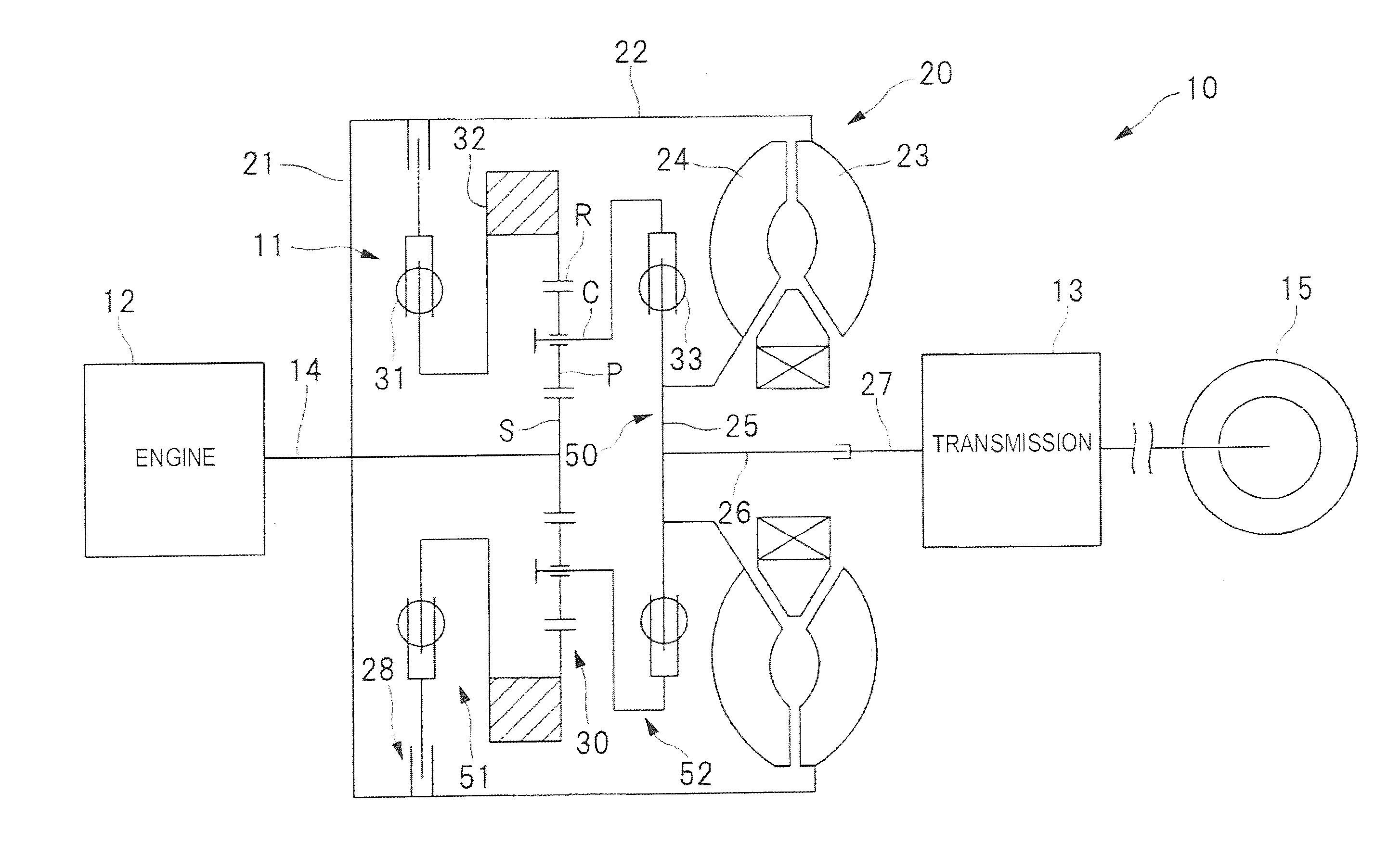
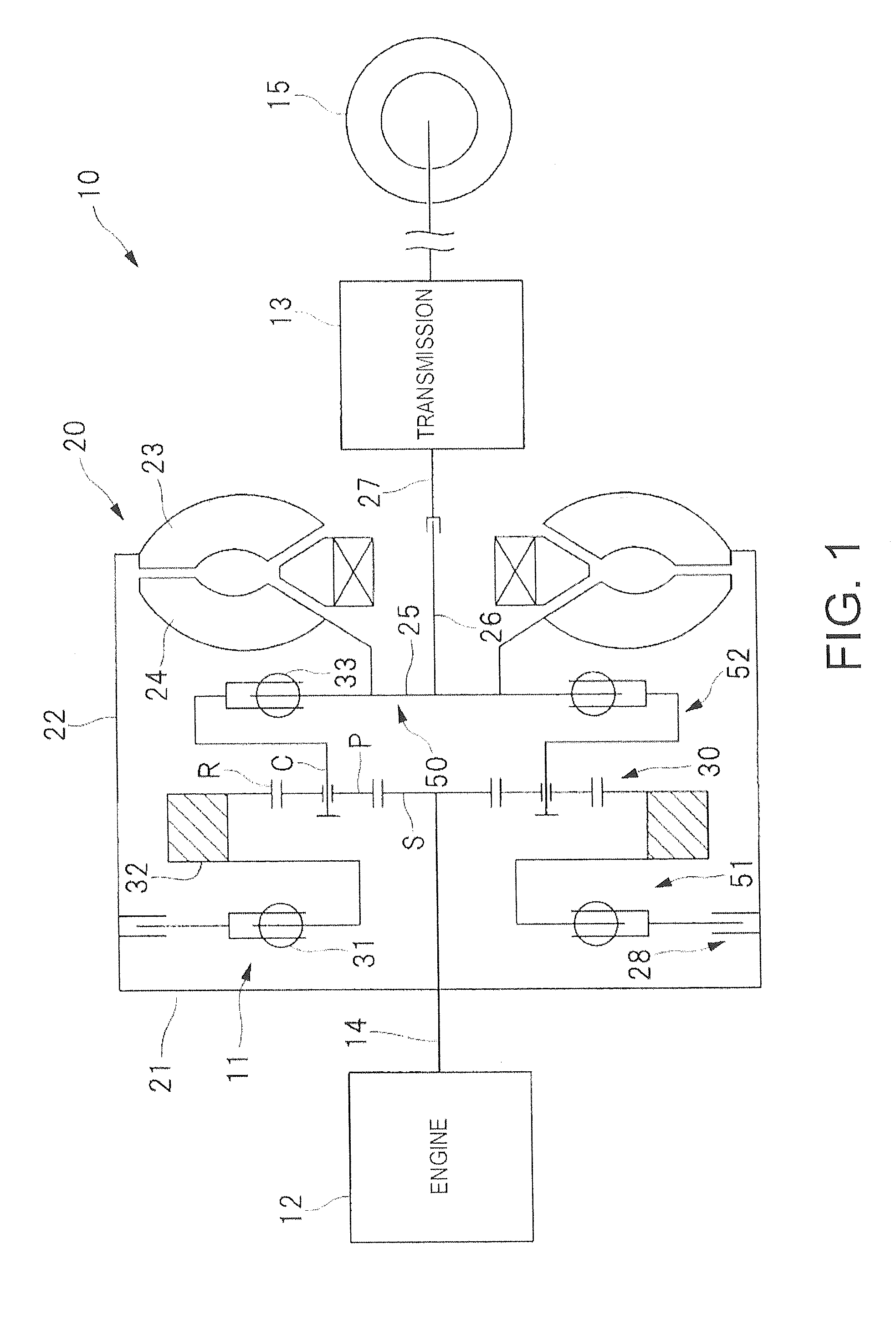
[0014]Hereinafter, an implementation of the present disclosure is described in detail based on the accompanying drawings. FIG. 1 is a schematic diagram illustrating a power unit 10 mounted on a vehicle. A damper device 11 which is an implementation of the present disclosure is assembled to the power unit 10 illustrated in FIG. 1. As illustrated in FIG. 1, the power unit 10 includes an engine 12 which is an internal combustion engine, and a transmission 13 connected to the engine 12 via the damper device 11. Thus, the damper device 11 is disposed between the engine 12 and the transmission 13, and the damper device 11 is used to damp torsional vibration which originates in vibrating forces of the engine 12. Note that the torsional vibration of the engine 12 means a torque variation resulting from, for example, combustion vibrating forces and unbalance inertial forces which act on a crankshaft 14 of the engine 12. Further, driving wheels 15 are connected to the transmission 13 via a di...


PUM


Abstract

A damper device is disposed between an engine and a transmission. The damper device includes a differential mechanism. The differential mechanism includes a first input element connected to the engine, a second input element connected to the engine, and an outputting element connected to the transmission. The damper device also includes a first spring disposed between the engine and the first input element, an inertia member disposed between the first spring and the first input element, and a second spring disposed between the transmission and the outputting element.

Description

CROSS-REFERENCE TO RELATED APPLICATION(S)[0001]The present application claims priority from Japanese Patent Application No. 2013-050700 filed on Mar. 13, 2013, the entire contents of which are hereby incorporated by reference.TECHNICAL FIELD[0002]The present disclosure relates to a damper device disposed between an engine and a transmission.BACKGROUND OF THE INVENTION[0003]In order to reduce torsional vibration transmitted from an engine to a transmission, a damper device is disposed between the engine and the transmission. As such a damper device, a damper device provided with two flywheels coupled via a spring has been proposed (see PCT International Publication No. WO2012 / 66680). The torsional vibration of the engine can be suppressed by coupling the two flywheels via the spring. A conventional damper device is designed by adjusting mass and a spring constant of each member which constitutes the damper device to offset a resonance point (specific frequency) of the damper device f...

Claims


Application Information

Patent Timeline
Patent Type & Authority Patents(United States)
IPC IPC(8): F16H47/08F16F15/14
CPCF16F15/1478F16F15/1206F16H45/02
Inventor MURAKAMI, MAMORU
Owner SUBARU CORP
Why Eureka
Try Eureka