Processor arrangement for multi mode wireless device

a wireless device and multi-mode technology, applied in the field of multi-mode wireless device processing arrangement, can solve the problems of increasing the space required within the wireless device for the radio components, increasing the power consumption in use, and inevitably increasing the cost of hardware duplication, and achieves high single-mode performan

Active Publication Date: 2015-03-03
AVAGO TECH INT SALES PTE LTD
View PDF19 Cites 6 Cited by
  • Summary
  • Abstract
  • Description
  • Claims
  • Application Information

AI Technical Summary

Benefits of technology

[0011]In this aspect, a processor arrangement is provided for a device that is capable of operating simultaneously with a cellular network (such as GSM, CDMA, W-CDMA, LTE, etc., etc.) and with a non-cellular network (such as WLAN IEEE802.11, BLUETOOTH® wireless technology, etc.). This simultaneous operation is achieved whilst keeping down the amount of silicon hardware required, which keeps down manufacturing costs, reduce errors that might arise in otherwise complex hardware, reduce power consumption in use and also keep down the space taken up by the hardware components. Moreover, it is expected that future cellular standards (including for example those arising from the 3rd Generation Partnership Project (3GPP)) will incorporate elements from non-cellular or machine-to-machine technology. Arranging the device in this way will facilitate adoption of such standards.
[0012]In an embodiment, the first processor is provided by a single chip. In an embodiment, the second processor is provided by a single chip. In an embodiment, the physical layer 1 processing for both the cellular radio communications and the non-cellular radio communications is provided by a single chip. In an other embodiment, the first and second processors are provided by a single chip. In yet another embodiment, the first and second processors and the physical layer 1 processing for both the cellular radio communications and the non-cellular radio communications are provided by a single chip. All of these embodiments serve to keep down the number of silicon devices that need to be used to provide the required functionality.
[0014]In an embodiment, the first and second processors are dynamically reconfigurable such that: the first processor can be selectively reconfigured to provide control processing for both physical layer 1 processing and processing for data link layer 2 for the cellular radio communications, and the second processor can be selectively reconfigured to provide control processing for both physical layer 1 processing and processing for data link layer 2 for the non-cellular radio communications. This embodiment provides a flexible arrangement that can be reconfigured to separate out the control and processing of the cellular radio communications and the non-cellular radio communications to the first and second processors respectively if needs require.
[0015]In an embodiment, the first and second processors are dynamically reconfigurable such that: the first processor and the second processor can be reconfigured to provide shared control processing for both physical layer 1 processing and processing for data link layer 2 selectively for the cellular radio communications or the non-cellular radio communications. In this embodiment, all of the processor resources are allocated to cellular-only or non-cellular-only use if required, which allows the arrangement to achieve high single-mode performance.

Problems solved by technology

This duplication of hardware inevitably raises costs and increases power consumption in use, and also increases the space required within the wireless device for the radio components.
Power consumption is a particular concern when the cellular and non-cellular components are to be used simultaneously.
However, compared to a conventional non-SDR radio system having bespoke hardware, a SDR is relatively inefficient on power usage and often has poor dynamic range.
Again, there is only a single radio front end and the SDR cannot be communicating with a cellular network and a non-cellular network simultaneously.

Method used


Image

  • Processor arrangement for multi mode wireless device
  • Processor arrangement for multi mode wireless device
  • Processor arrangement for multi mode wireless device

Examples


Embodiment Construction

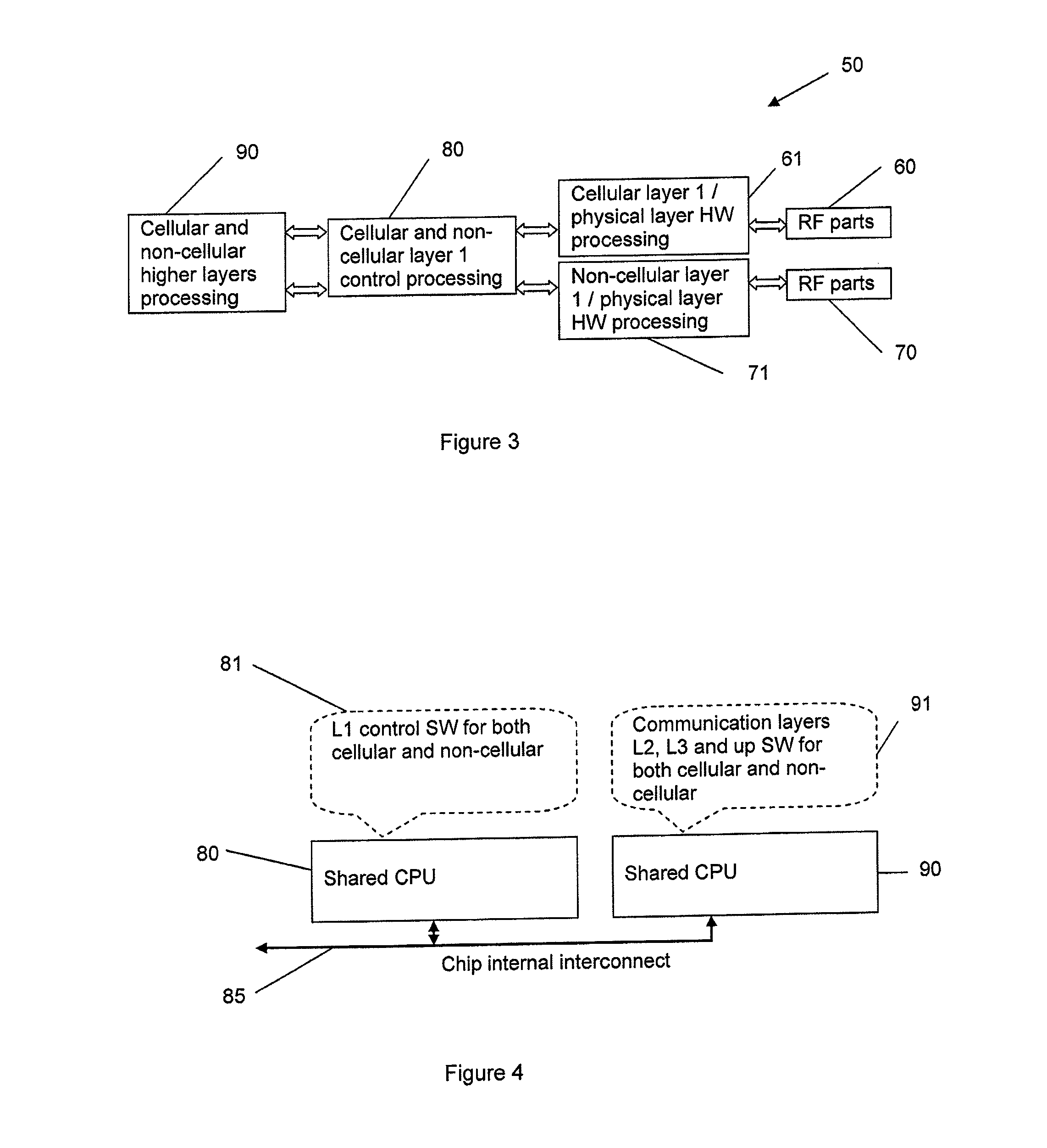
[0030]Referring to FIG. 3, there is shown schematically the main hardware components of an example of a multi mode wireless device 50 according to an embodiment of the present invention. This example is a dual mode device 50 capable of operating on both cellular and non-cellular networks, and, in the preferred embodiments, in general is capable of operating on both cellular and non-cellular networks simultaneously. This has the advantage for example that the device 50 can be used for voice communication (via the cellular network) and be in data communication (via the non-cellular network) simultaneously. A user can therefore be receiving or transmitting a data file and holding a telephone voice conversation on the device at the same time. As another example, a M2M (machine-to-machine) gateway type device can simultaneously receive data and transmit data (typically on a non-cellular network and on a cellular network respectively, though other arrangements are possible).

[0031]In this ...


PUM


Abstract

A multi mode wireless device can communicate with cellular and non-cellular networks. The device has first and second processors in communication with each other. In one arrangement, the first processor provides control processing for physical layer 1 processing for both the cellular and the non-cellular radio communications in parallel, and the second processor provides processing for data link layer 2 for both the cellular and the non-cellular radio communications in parallel, and the device can communicate with the cellular and non-cellular networks simultaneously. In another arrangement, the first processor provides control processing for physical layer 1 processing for both the cellular and the non-cellular radio communications in parallel, and the second processor provides processing for data link layer 2 and all layers above layer 2 in the device for both the cellular and the non-cellular radio communications in parallel.

Description

CROSS-REFERENCE TO RELATED APPLICATIONS[0001]This application is a continuation of U.S. application Ser. No. 13 / 173,767, filed Jun. 30, 2011, which is hereby incorporated herein in its entirety by reference. This application also claims priority to and the benefit of United Kingdom patent application number GB 1111160.6, filed on Jun. 30, 2011.FIELD OF THE INVENTION[0002]The present invention relates to a processor arrangement for a multi mode wireless device.BACKGROUND OF THE INVENTION[0003]Multi mode wireless devices that are compatible with more than one form of data transmission or network are known. Such devices include for example mobile devices such as mobile phones, personal digital assistants, etc., and M2M (machine-to-machine) gateway devices. A particular type of multi mode wireless device, often termed a dual mode device, contains both cellular and non-cellular radios which are used for voice and data communication respectively. Examples of cellular technologies include ...

Claims


Application Information

Patent Timeline
Patent Type & Authority Patents(United States)
IPC IPC(8): H04B7/00H04M1/00H04W88/06
CPCH04W88/06
Inventor TALVITIE, HANNU TAPANIKALTIOKALLIO, KIMPOGOSOVA, EKATERINA
Owner AVAGO TECH INT SALES PTE LTD
Why Eureka
Try Eureka