Method and a placement tool for the manufacture of a non-crimp fabric

a technology of placement tool and non-crimp fabric, which is applied in the manufacture of butter, cheese, domestic applications, etc., can solve the problems of reducing placement performance and reducing the difficulty of separation of fibre mats from tool surfaces, so as to achieve no effect, greatly reduce effects, and improve placement performan

Active Publication Date: 2015-03-10
AIRBUS OPERATIONS GMBH
View PDF10 Cites 0 Cited by
  • Summary
  • Abstract
  • Description
  • Claims
  • Application Information

AI Technical Summary

Benefits of technology

[0003]The object of the present invention is to create a method for placing fibre-reinforced pre-impregnated planar semi-finished products on the placement tool for the manufacture of a fibre mat, which removes the above-cited disadvantages and has a higher placement performance and also has no effects, or greatly reduced effects, on health or the environment, and also to create a placement tool for such a method.
[0005]In an inventive method for placing fibre reinforced pre-impregnated planar semi-finished products on a placement tool for the manufacture of a fibre mat a placement film is firstly fixed on the placement tool for purposes of holding the semi-finished products by means of the application of a vacuum. The semi-finished products are then laid down by layers on the placement film as skin plies. After the build-up of the mat, i.e. laminate, the latter is transferred onto a subsequent production means by pivoting the placement tool and subsequently releasing the vacuum. The placement film is then removed from the first skin ply and the subsequent treatment of the mat can begin. In the inventive solution it is particularly advantageous that the fixing of the semi-finished products on the placement tool takes place without a fluid adhesion promoter, but rather by means of a placement film that is simple to apply and remove. This enables on the one hand an increased placement performance, since on the one hand the application of the adhesion promoter and the cleaning of the placement tool are omitted, and there is also a significant reduction or complete elimination of any risks to health and the environment. In particular the speed of placement of the first skin ply is significantly increased. The placement film serves, so to speak, as surface protection for the tool surface and together with a sufficient retention of the fibre mat, i.e. its first skin ply, at the same time, by virtue of the standard impregnation of the semi-finished products on the film, allows a simple and rapid release from both the tool surface and also the first skin ply for purposes of transfer, or after transfer, for example, of the fibre mat to a downstream work station.
[0009]An inventive placement tool for placing fibre-reinforced planar semi-finished products so as to form a fibre mat has a multiplicity of holes introduced into its tool surface, which can be connected in fluid terms with an evacuation device. The multiplicity of holes allows even and extensive retention that is free of creases and bubbles of a fabric laid down on the tool surface, such as, for example, a placement film for purposes of holding the semi-finished products.
[0010]In one example of embodiment the holes are subdivided into hole arrays that can be activated separately from one another. In this manner it is possible firstly to fix the placement film securely on the tool surface by means of the removal of air by suction, and then to compact the skin plies laid down on the placement film by means of at least an intermediate level of vacuum, without this having a negative effect on the fixing of the placement film.

Problems solved by technology

However, disadvantages relating to the adhesion promoter include both its labour-intensive application onto the tool surface, and also the time-intensive cleaning of the tool surface after the fibre mat has been released, with the result that the placement performance is markedly reduced.
In principle it is also possible to position the material on the tool surface without a fluid adhesion promoter, but the fibre mat can then only be separated from the tool surface with great difficulty.

Method used


Image

  • Method and a placement tool for the manufacture of a non-crimp fabric
  • Method and a placement tool for the manufacture of a non-crimp fabric
  • Method and a placement tool for the manufacture of a non-crimp fabric

Examples


Embodiment Construction

[0018]In what follows the same design elements bear the same reference numbers, wherein in the event of a plurality of the same design elements in one figure, only some of the elements are provided with a reference number, in the interests of clarity.

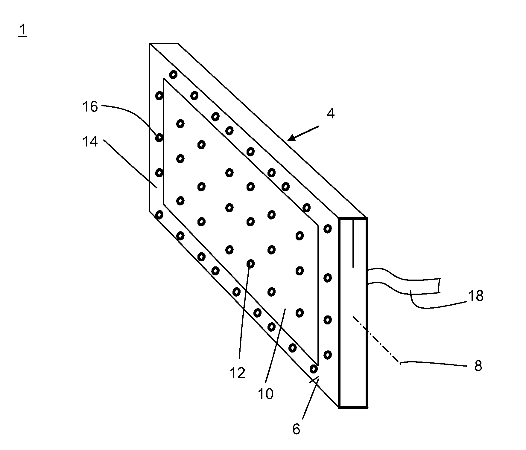
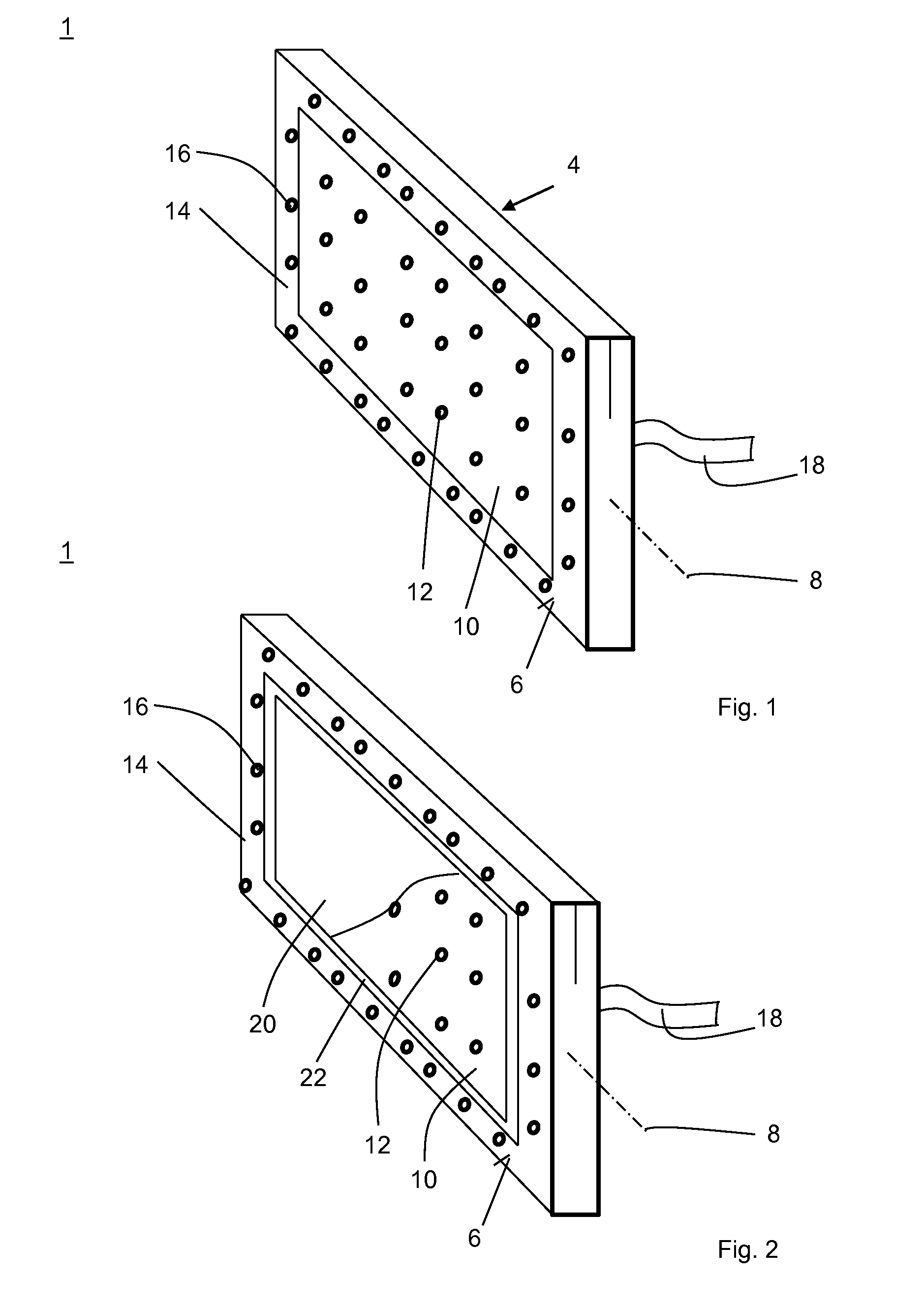
[0019]FIG. 1 shows an inventive placement tool 1 for the manufacture of a fibre mat or laminate 2 (see FIG. 7). The fibre mat 2 forms, for example, the skin of an approximately 16 m long shell element of an aircraft fuselage, which is composed of four shell elements, which are connected with one another on their longitudinal sides.

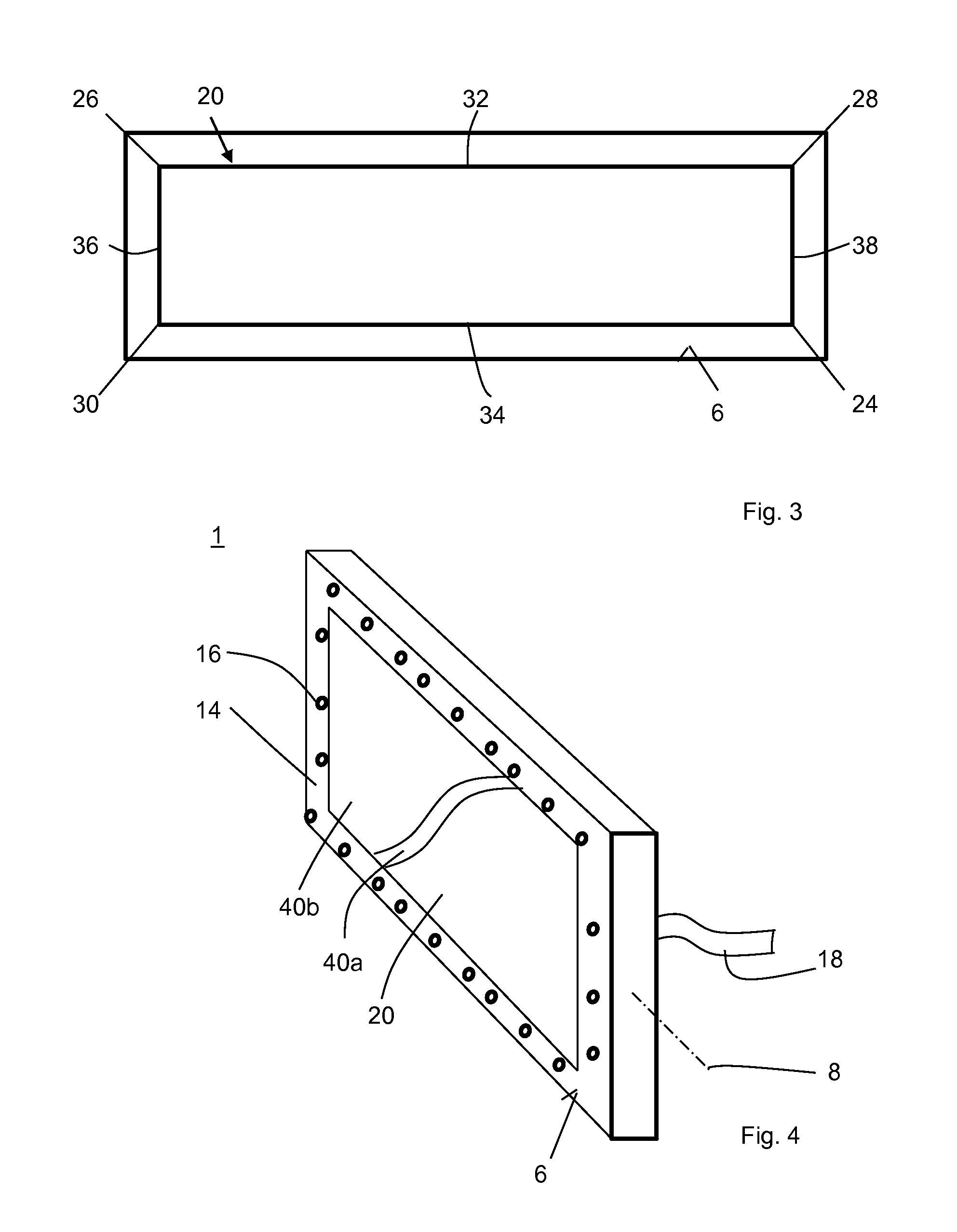
[0020]The placement tool 1 has an approximately rectangular body 4 with a vertically orientated tool surface 6, and can be pivoted about its longitudinal axis 8. The tool surface 6 is designed as a close match to the contour of the inner circumference of the aircraft fuselage and is appropriately curved in a concave manner (not shown) along the longitudinal axis 8. It has an inner hole array 10 with a multipli...


PUM

PropertyMeasurementUnit
vacuumaaaaaaaaaa
adhesionaaaaaaaaaa
speedaaaaaaaaaa

Abstract

Disclosed is a method for placing fiber-reinforced, pre-impregnated, planar semi-finished products on a placement tool for the manufacture of a non-crimp fabric, wherein a placement film is clamped on the placement tool for purposes of holding the non-crimp fabric, and by means of evacuation and / or the application of pressure is fixed in position on the placement tool and / or can be released from the latter. Also disclosed is a placement tool for the execution of such a method.

Description

TECHNICAL FIELD[0001]The present invention concerns a method for placing fibre-reinforced pre-impregnated planar semi-finished products on a placement tool for the manufacture of a fibre a non-crimp fabric (fibre mat), and also a placement tool for the execution of such a method.BACKGROUND OF RELATED ART[0002]Methods for placing prepregs, i.e. fibre-reinforced pre-impregnated planar semi-finished products on a placement tool for the manufacture of a fibre mat are generally known as “automated fibre placement” (AFP) or “automated tape placement” (ATP) methods. Here semi-finished products, which have fibres that are pre-impregnated with a thermosetting or thermoplastic material, for example, carbon fibres that are oriented relative to one another, are laid down on a tool that is a close match to the final contour. The significant difference between the AFP and the ATP process consists in the fact that in the ATP process narrow material tapes, i.e. semi-finished product tapes, are laid...

Claims


Application Information

Patent Timeline
Patent Type & Authority Patents(United States)
IPC IPC(8): B29C65/00B29C43/02B29D24/00B29D29/00B29B15/00B29C39/14B29C49/08B29C55/00B29C67/20B29D7/00B29C43/10A01J21/00A01J25/12A21C3/00A21C11/00A23G1/20A23G3/02A23P1/00B28B11/08B28B21/36B29C55/28B29C49/00B29C51/00B32B37/00B29C45/00B29C47/00B29C33/68B29C37/00B29C70/30B29C70/44B29C70/54B29L31/30
CPCB29C70/30B29C33/68B29C37/0067B29C70/44B29C70/541B29L2031/3082Y10T156/1744
Inventor LEMCKAU, THOMASHARDERS, SONKEKERCHNAWE, SOPHIE
Owner AIRBUS OPERATIONS GMBH
Why Eureka
Try Eureka