
Method and apparatus for retaining a remaining back-off time in CSMA/CA based on a threshold

a technology of back-off time and threshold, applied in the direction of synchronisation arrangement, frequency-division multiplex, instruments, etc., can solve the problems of inability to provide driving support system, transmission, transmission, information not being transmitted, etc., and achieve the effect of reducing the possibility of transmission data colliding with at least one peripheral terminal

Inactive Publication Date: 2015-03-10
MITSUBISHI ELECTRIC CORP
View PDF17 Cites 0 Cited by
  • Summary
  • Abstract
  • Description
  • Claims
  • Application Information

AI Technical Summary

Benefits of technology

The communication control apparatus described in this patent allows for independent control over the timing of transmitting data based on the time difference between the last peripheral terminal reception time and the transmission request time. This is possible even without performing carrier sensing to confirm if the peripheral terminal is in communication. This helps to reduce the likelihood of data collisions and ensures efficient communication.

Problems solved by technology

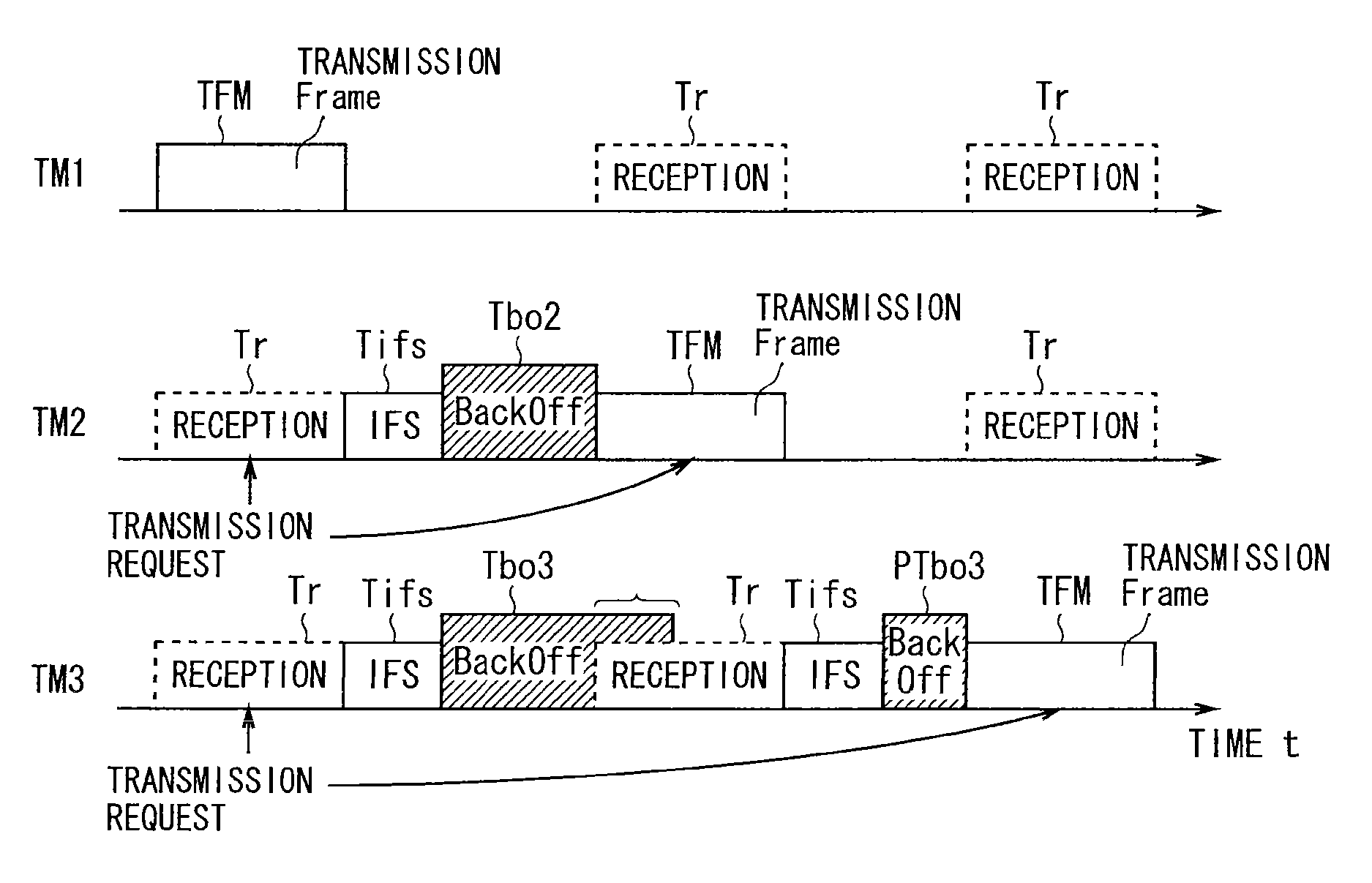
In the CSMA / CA scheme, in a case of periodically transmitting the terminal information, if the number of communication terminals within a communication range increases, the reliability of communication would be deteriorated to make it impossible to provide the driving support system, because: each terminal repeatedly waits for a back-off time before transmission so that congestion occurs that makes transmission impossible; transmission timings after the back-off time coincide with each other with a higher probability so that wireless communication packets collide with each other; collision occurs with a wireless communication packet of a hidden terminal, that is, a terminal that cannot be found by carrier sensing.
Moreover, even though congestion or packet collision occurs, the application that periodically transmits the terminal information cannot detect the occurrence of congestion or collision, and therefore in a next period, transmission is requested at the same timing and in the same period by the CSMA / CA.
Thus, the possibility that information failing to be transmitted will be accumulated or the possibility that transmitted packets will collide with each other is still not reduced.

Method used


Image

  • Method and apparatus for retaining a remaining back-off time in CSMA/CA based on a threshold
  • Method and apparatus for retaining a remaining back-off time in CSMA/CA based on a threshold
  • Method and apparatus for retaining a remaining back-off time in CSMA/CA based on a threshold

Examples


embodiment 1

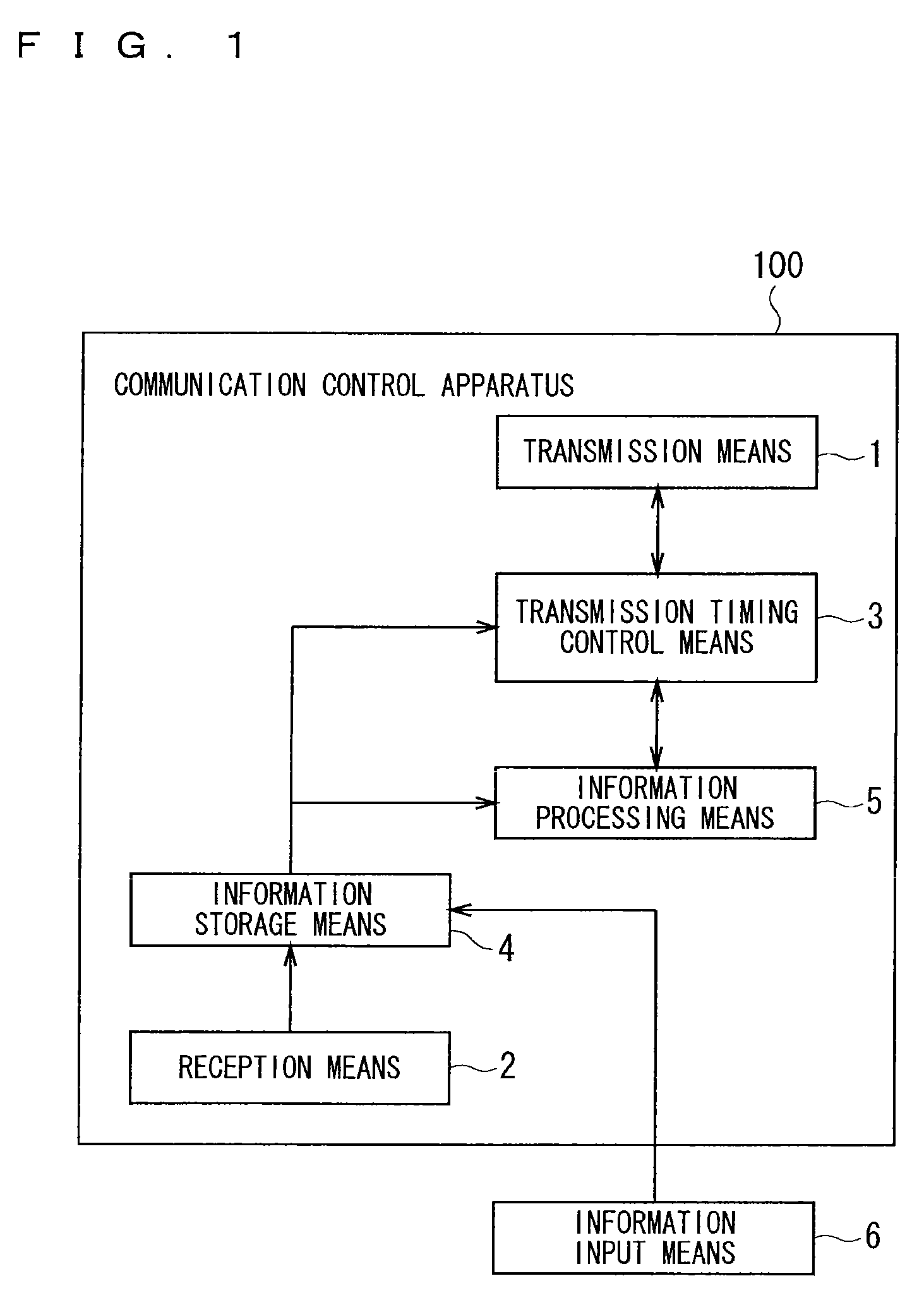
[0047]FIG. 1 is a block diagram showing an outline configuration of a communication control apparatus 100 according to the present invention. In this description, the same or equivalent parts of the configuration are denoted by the same reference numerals, and this applies to the whole of the description.

[0048]The communication control apparatus 100 is mounted in each of a plurality of terminals. Through the communication control apparatus 100, wireless communication is performed between the terminals. Here, the communication control apparatus 100 is a main part for performing communication that is mounted in the terminal, and serves as a main part of a portable communication terminal such as a wireless LAN (Local Area Network) terminal or a mobile phone, a communication terminal mounted on a vehicle such as an ETC (Electronic Toll Collection System), or a stationary communication apparatus such as a infrastructure including a roadside device, a base station, or the like.

[0049]For t...

embodiment 2

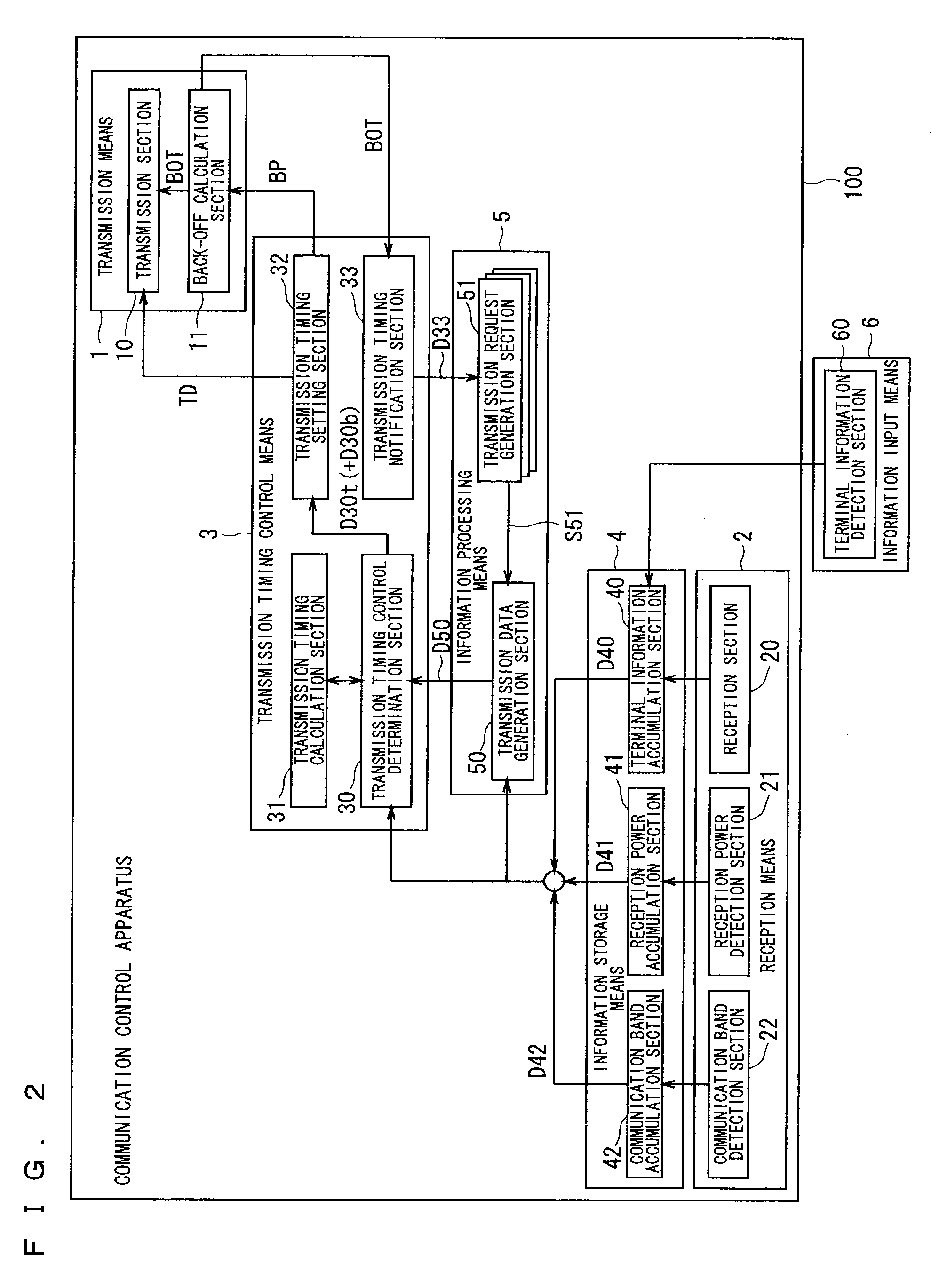
[0182]The transmission means 1B of the embodiment 2 sets transmission power by the transmission power switching section 12, in accordance with a request (congestion control information D70) from the congestion control means 7.

[0183]In the embodiment 2, the information storage means 4 also stores the number of peripheral terminals in communication, and transmission power, a transmission period, and a (peripheral terminal) communication band utilization rate that are received from the peripheral terminal, and the like.

[0184]In the embodiment 2, the information processing means 5 changes the transmission request timing (timing for outputting the transmission request signal S51) that defines a transmission period, in accordance with a request from the transmission timing control means 3.

[0185]In the embodiment 2, the congestion control means 7 uses the information D40 to D42 obtained from the information storage means 4, to control the transmission power and the transmission period and ...

embodiment 3

[0243]FIG. 20 is a block diagram showing a detailed configuration of a communication control apparatus 102 according to the present invention. The same part as that of the embodiments 1 and 2 is denoted by the same reference numeral, and a detailed description thereof is omitted as appropriate.

[0244]A configuration of the embodiment 3 of the present invention, similarly to the configuration of the embodiment 2 shown in FIG. 15, includes transmission means 1C (corresponding to the transmission means 1B), the reception means 2, transmission timing control means 3C (corresponding to the transmission timing control means 3), the information storage means 4, information processing means 5C (corresponding to the information processing means 5), the information input means 6, and the congestion control means 7.

[0245]Accordingly, the communication control apparatus 102 of the embodiment 3 is different from that of the embodiment 2 shown in FIG. 15, in that the transmission timing control me...


PUM


Abstract

A communication control apparatus in which, when requested to transmit (transmission) terminal information from information processing means, a transmission timing controller obtains past own terminal communication band information from an information storage, and determines whether or not to control a transmission timing. Moreover, the transmission timing controller calculates a back-off parameter for the control based on a past reception power information history that is obtained from the information storage, and sets a back-off parameter to a transmission device.

Description

TECHNICAL FIELD[0001]The present invention is an invention relating to a communication control apparatus that is mounted on a terminal for achieving efficient wireless communication between terminals, and to a communication control method, and particularly relating to a communication control apparatus capable of improving communication quality by making such a control that distributes a transmission timing for transmitting information.BACKGROUND ART[0002]Conventionally, a communication apparatus for wireless communication between terminals has adopted the CSMA / CA (Carrier Sense Multiple Access with Collision Avoidance) scheme as an access scheme, in order that the terminal can achieve wireless communication in an autonomous distributed manner.[0003]The CSMA / CA scheme is generally known as a method that avoids wireless communication collision, in which when a terminal wirelessly transmits information, the terminal waits for a random back-off time before transmission and then performs...

Claims


Application Information

Patent Timeline
Patent Type & Authority Patents(United States)
IPC IPC(8): H04W74/08H04W56/00
CPCH04W74/085H04W56/0045
Inventor HAMADA, YUJIGOTO, YUKIOIKAWA, MASAHIKOMORITA, SHIGEKI
Owner MITSUBISHI ELECTRIC CORP
Learn More