

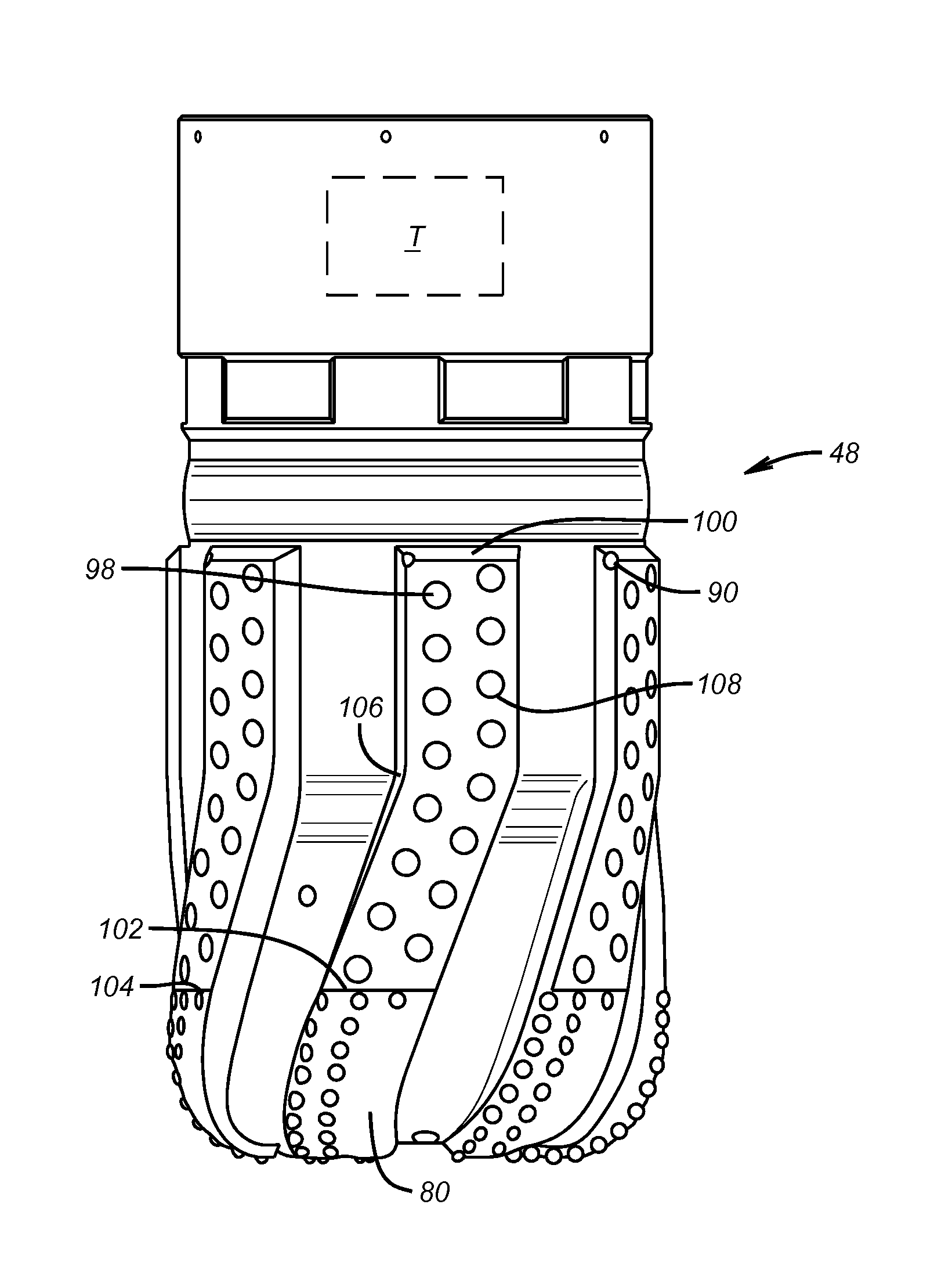
Turbine driven reaming bit with blades and cutting structure extending into concave nose
a turbine-driven, cutting-structure technology, applied in the direction of borehole drives, cutting machines, drilling machines and methods, etc., can solve the problems of limited torque that can be delivered to the bit, difficult to achieve ideal boreholes, and complicated drive systems, etc., to achieve enhanced high speed stability, low torque fluctuation, and increased exposure
- Summary
- Abstract
- Description
- Claims
- Application Information
AI Technical Summary
Benefits of technology
Problems solved by technology
Method used
Image

Examples
Embodiment Construction
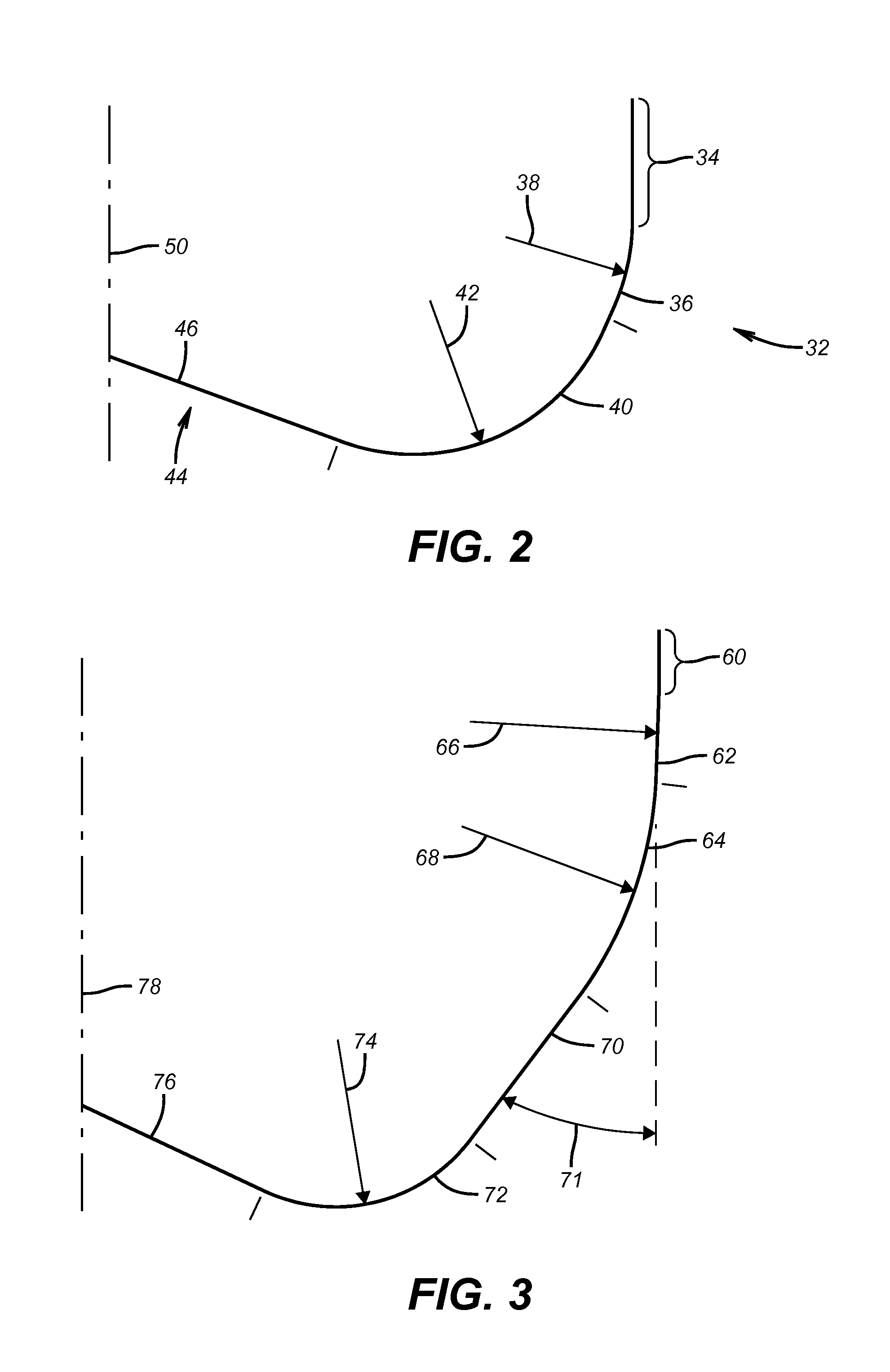
[0015]FIG. 2 shows a profile 32 that begins below the gage segment 34. The next segment is shown as a single segment 36 with a single radius 38 which is preferably tangent to gage segment 34 but it can also be a plurality of arcuate segments with differing radii, which blend into each other. Transition segment 40 is adjacent to segment or segments 36 and curves around with a radius 42 into the leading part or nose of the profile and joins the tapered segment 46 to define the concave cone 44. Segment 46 extends to the centerline 50. Radius 38 and 42 can also be combined into large, single radius. The profile length (PL) is defined as the sum of the lengths of segment(s) 36, 40 and 46. The bit size (BS) is defined in a plane perpendicular to the centerline 50 and is twice the distance from the centerline 50 to the gauge segment 34 that is preferably cylindrical. The use of an arcuate profile from the gage segment 34 to the nose 44 and the elimination of long, low angle tapered section...
PUM
 Abstract
Description
Claims
Application Information