High-rate anaerobic pool bioreactor

a bioreactor and high-rate technology, applied in the field of bioreactors, can solve the problems of high exploitation cost of aerobic digestion, time needed for the process, and complex equipment, and achieve the effects of reducing the operational loss over time, improving sedimentation, and increasing the conversion performance of the process

Inactive Publication Date: 2015-03-17
UNIV DEL VALLE
View PDF9 Cites 0 Cited by
  • Summary
  • Abstract
  • Description
  • Claims
  • Application Information

AI Technical Summary

Benefits of technology

[0018]Additionally, another object of the current invention is the optimization of the mix and contact processes between the biomass and the substrate to increase the conversion performance of the process.
[0019]Another object of the current invention is the implementation of a system of retention of the active biomass for the bioreactor to diminish its operational losses over time.
[0020]Particularly, another object of the current invention is to provide a process of biomass separation through improved sedimentation in horizontal laminar flow.

Problems solved by technology

Most of these systems require sophisticated and costly equipment to guarantee the satisfactory operation of the procedure.
However, the exploitation costs are much higher for aerobic digestion given the energetic costs necessary to add oxygen to the process.
Its disadvantage is the time needed for the process, which in some instances may take several days, but nevertheless, the capital costs may be than those for the aerobic treatment.

Method used


Image

  • High-rate anaerobic pool bioreactor
  • High-rate anaerobic pool bioreactor
  • High-rate anaerobic pool bioreactor

Examples


example 1

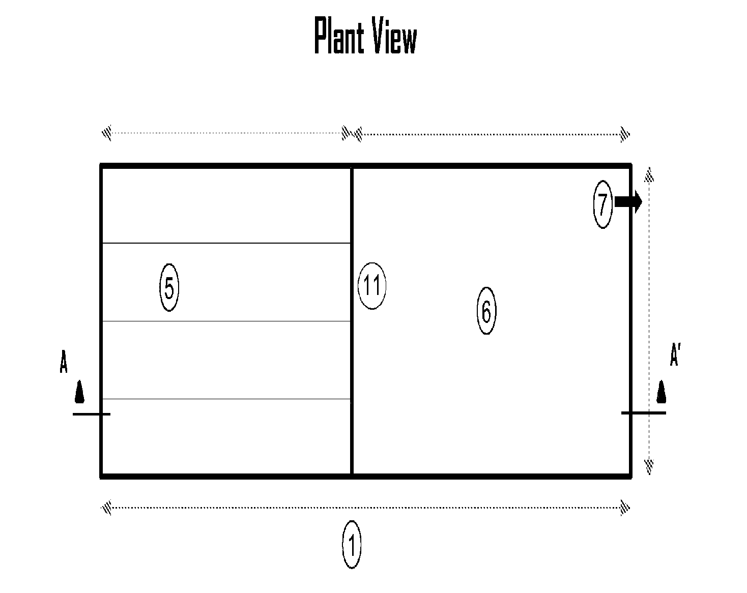
[0029]Experiment 1 evaluated a horizontal baffle anaerobic pond (HBAP) reactor, an HRAPB reactor of the invention with a built-in mix pond (MPAP) and a conventional anaerobic pond (CAP) reactor. The HBAP reactor presents to baffles placed at L / 3 and 2 L / 3. A flow-free space (0.80 m wide×1.70 m high) was left at the end of each horizontal baffle to permit water flow at the turn points. The HRAPB reactor equipped with MPAP was outfitted with a water input at the bottom followed by vertical flow through a reaction chamber. The residual water was fed by a multiple manifold type distribution system. Hence, the density resulting at the feed points (surface area of 8.8 m2) was 2.9 m2 / point of entry. Once the residual water flows through the reaction chamber and is mixed with the biomass in the HRAPB reactor with MPAP, it travels horizontally through an undisturbed sedimentation zone toward the exit. The transition zone between the mix chamber and the sedimentation zone was elaborated with ...

example 2

[0035]Experiment 2 evaluated the process performance for the HBAP, HRAPB reactor with MPAP and CAP in stationary state for 22 weeks with three different rates of hydraulic load according to the design presented in Table 3.

[0036]

TABLE 3Design of the experiment for the evaluation of process performance instationary state for HBAP, HRAPB reactors with MPAP and CAP.Configuration of theApplied flowMonitoringreactorrates (l / s)HRT (h)period (weeks)HBAP1.0 / 1.3 / 2.024.6 / 18.9 / 12.36MPAP1.1 / 1.5 / 2.326.0 / 19.3 / 12.66CAP0.9 / 1.3 / 1.825.3 / 17.2 / 12.76

[0037]The response to each rate of applied hydraulic load was evaluated for six weeks in stationary state, which was previously established in a two-week period.

[0038]Combined 12-h samples were taken in untreated waters and in the effluents from the reactors once per week, on the same day each week. The flow data were recorded each hour in each input flow on the day of the sampling. The flow rates of the effluent were measured volumetrically once per week to ...


PUM

PropertyMeasurementUnit
velocityaaaaaaaaaa
time of retentionaaaaaaaaaa

Abstract

The present application relates to a high-rate anaerobic pool bioreactor (“BLAAT”) as an improved processing unit for treating biodegradable wastewater, which allows the conversion of a low-performance rate traditional system, such as the anaerobic pool, into an efficient, compact system that enables clean energy to be recovered in the from of biogas. The application also describes a process for the anaerobic treatment of wastewater that uses said bioreactor, which optimizes the processes of mixing and contact between the biomass and the substrate and presents a novel process for separating out the biomass by means of improved sedimentation in horizontal laminar flow.

Description

RELATED APPLICATIONS[0001]This application is the United States National Stage of International Application No. PCT / IB2009 / 055447, filed Dec. 1, 2009, which was published as International Publication No. WO 2010 / 064195, and which claims benefit of Columbian Patent Application No. 8 128172 filed Dec. 2, 2008. Both applications are incorporated by reference in their entirety herewith.FIELD OF THE INVENTION[0002]The current invention is related with a bioreactor for high-rate anaerobic ponds (BHRAP) as an improved process unit for the treatment of residual biodegradable waters. It has four main components that characterize its design, construction, and operation. Herein, we will also relate to an anaerobic treatment process of residual waters that employs said bioreactor.BACKGROUND OF THE INVENTION[0003]In recent years, a considerable number of treatment systems have been developed for the purification of residual waters. Most of these systems require sophisticated and costly equipment...

Claims


Application Information

Patent Timeline
Patent Type & Authority Patents(United States)
IPC IPC(8): C02F3/28
CPCC02F3/28C02F3/2866C02F2301/022Y02E50/343Y02E50/30Y02W10/37
Inventor PENA VARON, MIGUEL RICARDO
Owner UNIV DEL VALLE
Why Eureka
Try Eureka