Motor controller and electric power steering device using the same
a technology which is applied in the direction of motor control for motor oscillation damping, emergency protective arrangement for automatic disconnection, dynamo-electric motor/converter starter, etc., can solve the problem of difficult downsizing of motor controller and electric power steering device, the possibility of motor controller controlling a polyphase motor, and the number of components increases. , to achieve the effect of suppressing the pulsation, simple configuration and low cos
- Summary
- Abstract
- Description
- Claims
- Application Information
AI Technical Summary
Benefits of technology
Problems solved by technology
Method used
Image
Examples
first embodiment
[0019
[0020]Hereinafter a first embodiment of the present invention is described in detail referring to the accompanying drawings.
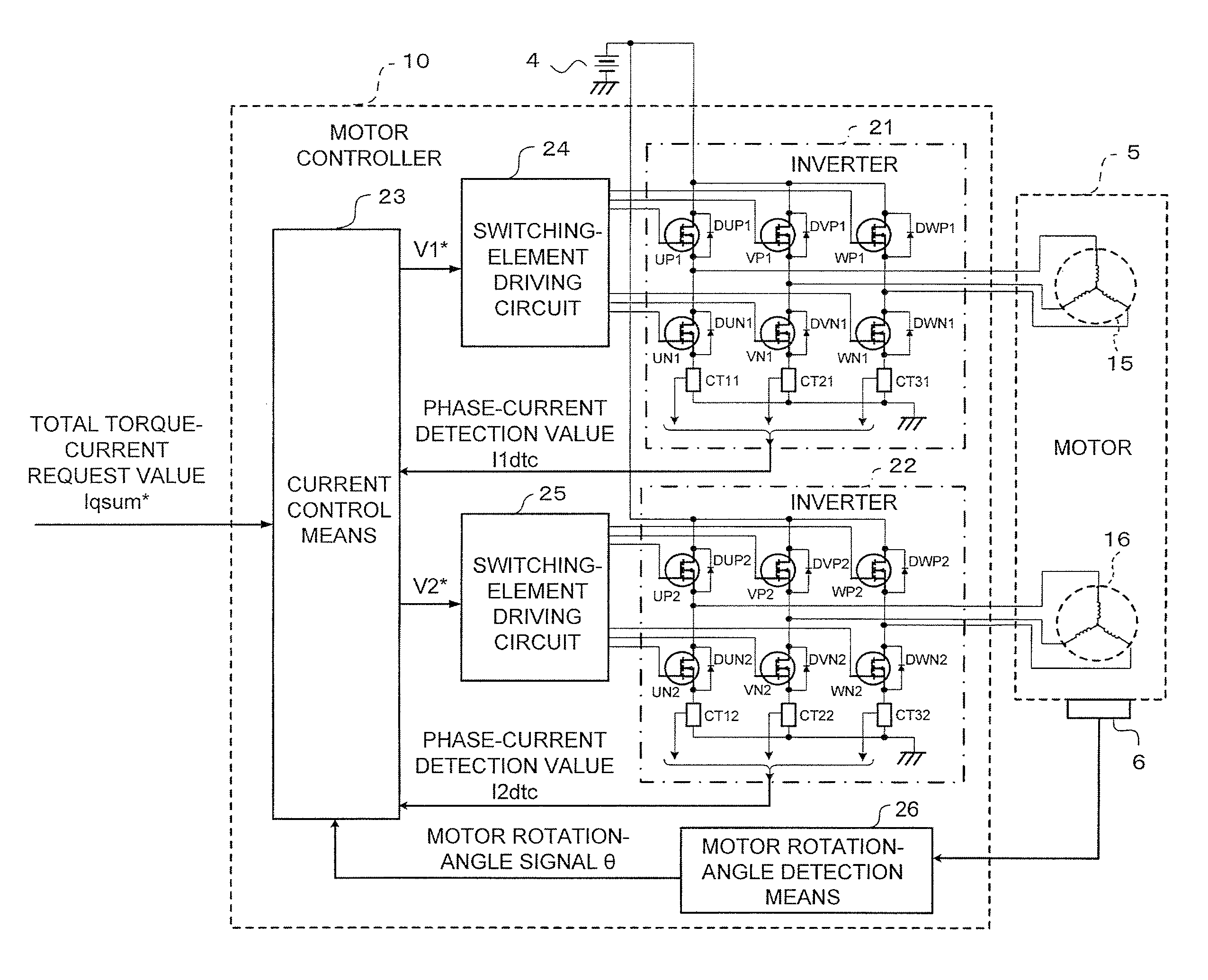
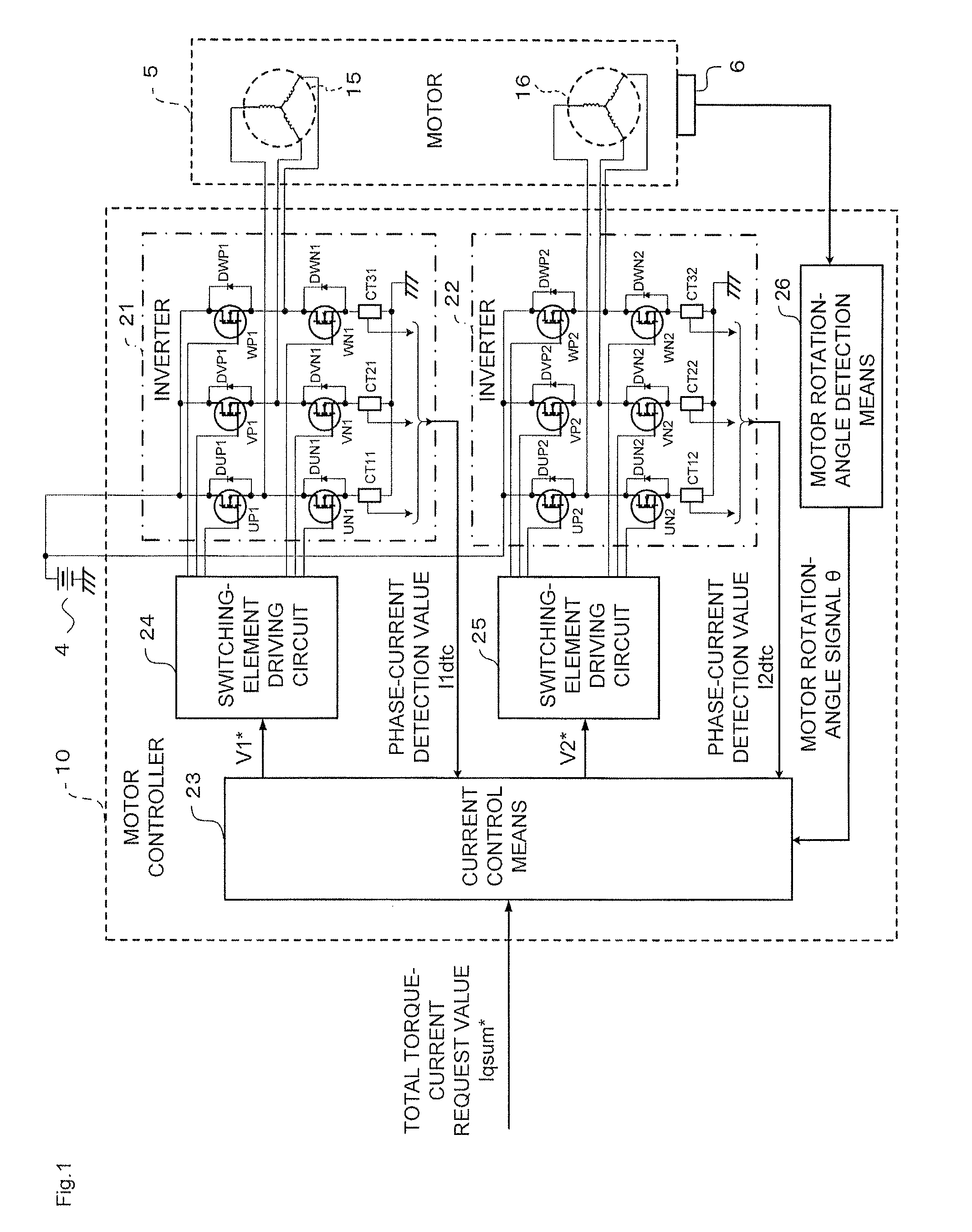
[0021]FIG. 1 is a block diagram schematically illustrating an overall configuration of a motor controller 10 according to the first embodiment of the present invention.
[0022]FIG. 1 illustrates not only the motor controller 10 but also a peripheral configuration relating to the motor controller 10. Specifically, the peripheral configuration includes a power source 4 (for example, an in-vehicle battery), a motor 5, and a motor rotation-angle sensor 6 for detecting a rotation angle of the motor 5.
[0023]In FIG. 1, the motor 5 includes a first winding set 15 having three phases, that is, a U1-phase, a V1-phase, and a W1-phase, and a second winding set 16 having three phases, that is, a U2-phase, a V2-phase, and a W2-phase. Each of the winding sets 15 and 16 respectively corresponding to a first system and a second system is obtained by connecting the three phas...
second embodiment
[0125
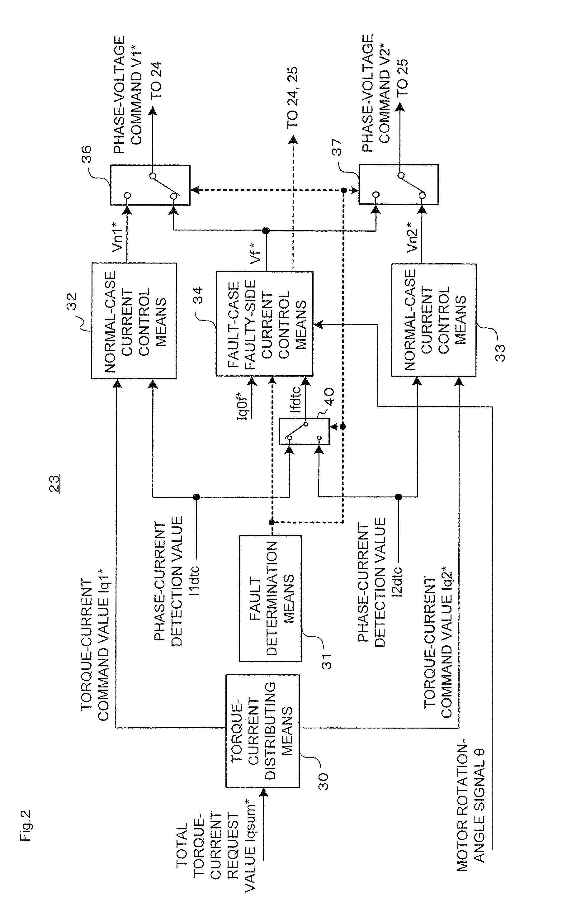
[0126]In the first embodiment (FIG. 2) described above, the currents in the normal winding driving system in the case of the fault are controlled by the normal-case current control means 32 and 33. However, as illustrated in FIG. 3, fault-case normal-side current control means 35 may be additionally provided so that the currents in the normal winding driving system in the case of a fault are controlled by the fault-case normal-side current control means 35 separately from the normal-case current control means 32 and 33 in a way different from the control for the normal operation.
[0127]FIG. 3 is a block diagram illustrating a functional configuration of current control means 23A according to a second embodiment of the present invention. The same components as those described above (see FIG. 2) are denoted by the same reference symbols or the same reference symbols followed by “A”, and the detailed description thereof is herein omitted.
[0128]The overall configuration of the motor...
third embodiment
[0186
[0187]Although not specifically referred to in the second embodiment (FIG. 3) described above, the fault-case normal-side current control means 35, which is included in the current control means 23A, may add a pulsating component at a low level or a high frequency to the current to be supplied to each of the windings of the normal winding driving system when a fault is detected by the fault determination means 31.
[0188]A third embodiment of the present invention, in which the pulsating component is added to the current to be supplied to each of the windings of the normal winding driving system, is hereinafter described referring to FIG. 3.
[0189]In this case, pulsation adding means for adding the pulsating component to the controlled current of the normal winding driving system can be provided, for example, in the fault-case normal-side current control means 35 of FIG. 3.
[0190]Specifically, in FIG. 3, a small pulsation at such a level as not to give a feeling of discomfort in st...
PUM
 Abstract
Description
Claims
Application Information
 - R&D
- Intellectual Property
- Life Sciences
- Materials
- Tech Scout
- Unparalleled Data Quality
- Higher Quality Content
- 60% Fewer Hallucinations
Browse by: Latest US Patents, China's latest patents, Technical Efficacy Thesaurus, Application Domain, Technology Topic, Popular Technical Reports.
© 2025 PatSnap. All rights reserved.Legal|Privacy policy|Modern Slavery Act Transparency Statement|Sitemap|About US| Contact US: help@patsnap.com


