AWG filter for wavelength interrogator

a wavelength interrogator and filter technology, applied in the field of wavelength discriminator, can solve the problems of limit reached and limited number of sensors

Active Publication Date: 2015-03-17
INTELLIGENT FIBER OPTIC SYST
View PDF1 Cites 19 Cited by
  • Summary
  • Abstract
  • Description
  • Claims
  • Application Information

AI Technical Summary

Problems solved by technology

A limit is reached in such an architecture, where the number of sensors is limited by the number of sine filters in the interrogator.

Method used


Image

  • AWG filter for wavelength interrogator
  • AWG filter for wavelength interrogator
  • AWG filter for wavelength interrogator

Examples


Embodiment Construction

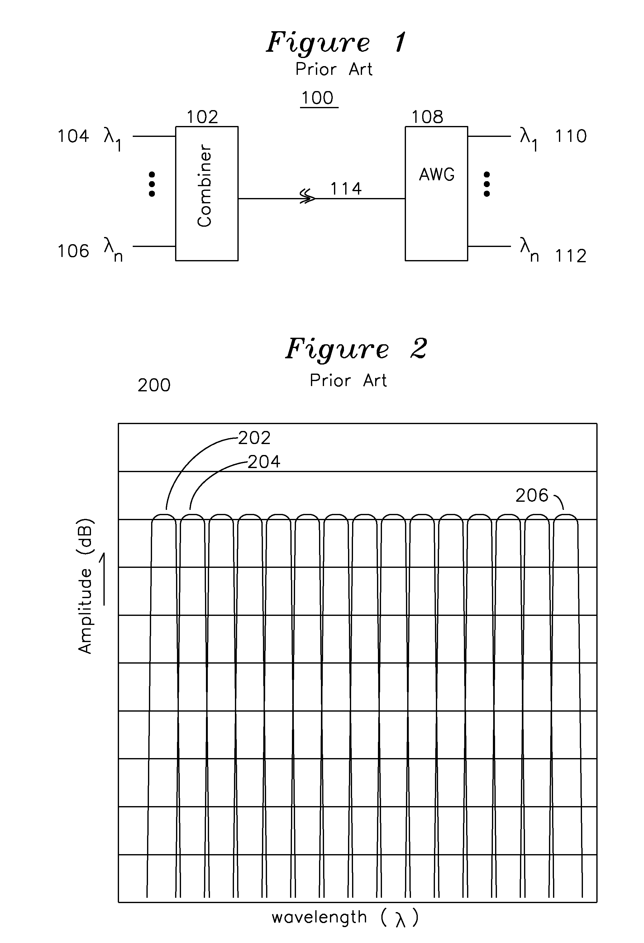
[0020]AWG filters are widely used in telecommunications to provide unique wavelength response in a WDM (wavelength division multiplexing) system which assigns adjacent wavelengths to independent communication sessions, and the AWG filter is utilized because it has multiple adjacent filtered channels, each with a flat response in a filtering range, and a skirt response region adjacent to, and on either side of, the flat response region.

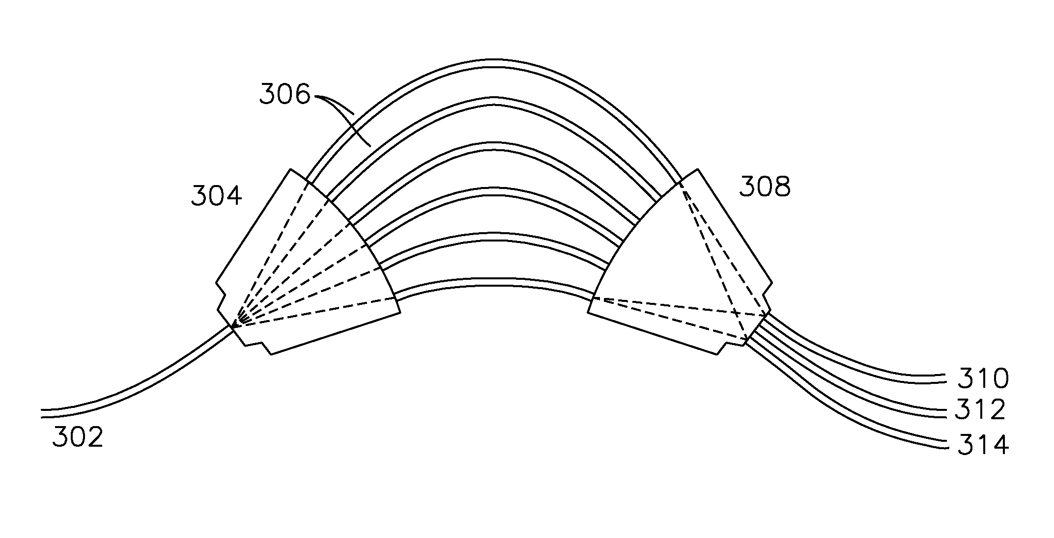
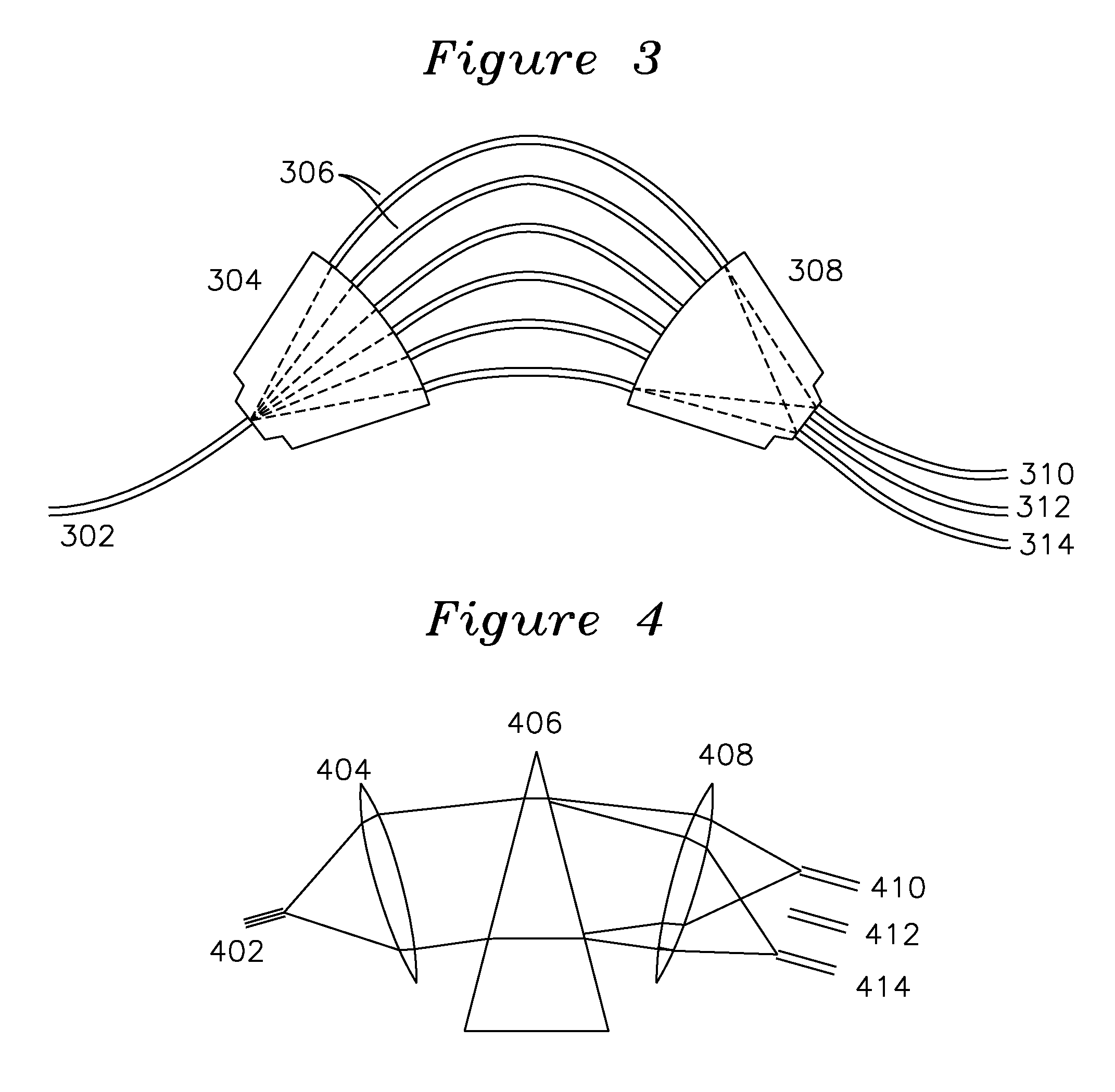
[0021]FIG. 1 shows a prior art AWG communication system. Individually modulated laser sources 104 at λ1 through 106 at λn modulate optical energy in distinct and non-overlapping wavelengths, such as an ITU wavelength grid. The wavelengths to be transmitted over a single fiber may be summed using a combiner 102, or an AWG for coupling the multiple sources at unique wavelengths to a single optical fiber 114 which carries the combined wavelength channel information to a remote station with AWG 108 for demultiplexing the wavelengths into individual wavelen...


PUM


Abstract

A wavelength interrogator is coupled to a circulator which couples optical energy from a broadband source to an optical fiber having a plurality of sensors, each sensor reflecting optical energy at a unique wavelength and directing the reflected optical energy to an AWG. The AWG has a detector coupled to each output, and the reflected optical energy from each grating is coupled to the skirt edge response of the AWG such that the adjacent channel responses form a complementary pair response. The complementary pair response is used to convert an AWG skirt response to a wavelength.

Description

[0001]The present invention was developed under NASA SBIR contract NNX11CG39P. The government has certain rights in the invention.FIELD OF THE INVENTION[0002]The present invention relates to a wavelength discriminator for fiber optic use. In particular, the present invention relates to arrayed waveguide grating (AWG) filter use in a wavelength interrogator.BACKGROUND OF THE INVENTION[0003]A wavelength interrogator typically uses a sine filter or other type of wavelength sensitive filter which has a monotonic response to a shift in incoming wavelength, with the wavelength interrogator coupled to a fiber Bragg grating (FBG) sensor, which may be place in series with other FBG sensors, each sensor having a corresponding wavelength discriminator. A limit is reached in such an architecture, where the number of sensors is limited by the number of sine filters in the interrogator.[0004]Additionally, the sine filters are individual components, each of which is tuned to operate in a particula...

Claims


Application Information

Patent Timeline
Patent Type & Authority Patents(United States)
IPC IPC(8): G02B6/34G01J3/02
CPCG01J3/0229G01J3/0218G01J3/1895G01J3/36G02B6/02057G02B6/2938H04J14/0256
Inventor BLACK, RICHARD J.COSTA, JOANNES M.FARIDIAN, FEREYDOUNMOSLEHI, BEHZADSOTOUDEH, VAHID
Owner INTELLIGENT FIBER OPTIC SYST
Why Eureka
Try Eureka