
Programmable robotic apparatus

a robotic apparatus and programmable technology, applied in the field of mobile robotic apparatus, can solve the problems of large time, effort and resources, and the need to provide and locate transmitters or other indicators, and the necessity to place such transmitters or other locators, and achieve the effect of reducing the cost of operation, saving time and effor

Inactive Publication Date: 2015-03-17
DEAN JASON A
View PDF29 Cites 0 Cited by
  • Summary
  • Abstract
  • Description
  • Claims
  • Application Information

AI Technical Summary

Problems solved by technology

Tasks such as mowing lawns are tedious and can be unpleasant, but are necessary.
One problem that is common to each of the robotic systems described above is the need to provide and to locate transmitters or other indicators of a desired path or boundary.
The necessity to place such transmitters or other locators involves considerable expenditure of time, effort, and funds, and may require precise measurements over considerable distances.
Alteration of the desired actions of the robotic apparatus may require further time, effort, and funds to change the configuration of the previously defined path or boundary.

Method used


Image

  • Programmable robotic apparatus
  • Programmable robotic apparatus
  • Programmable robotic apparatus

Examples


Embodiment Construction

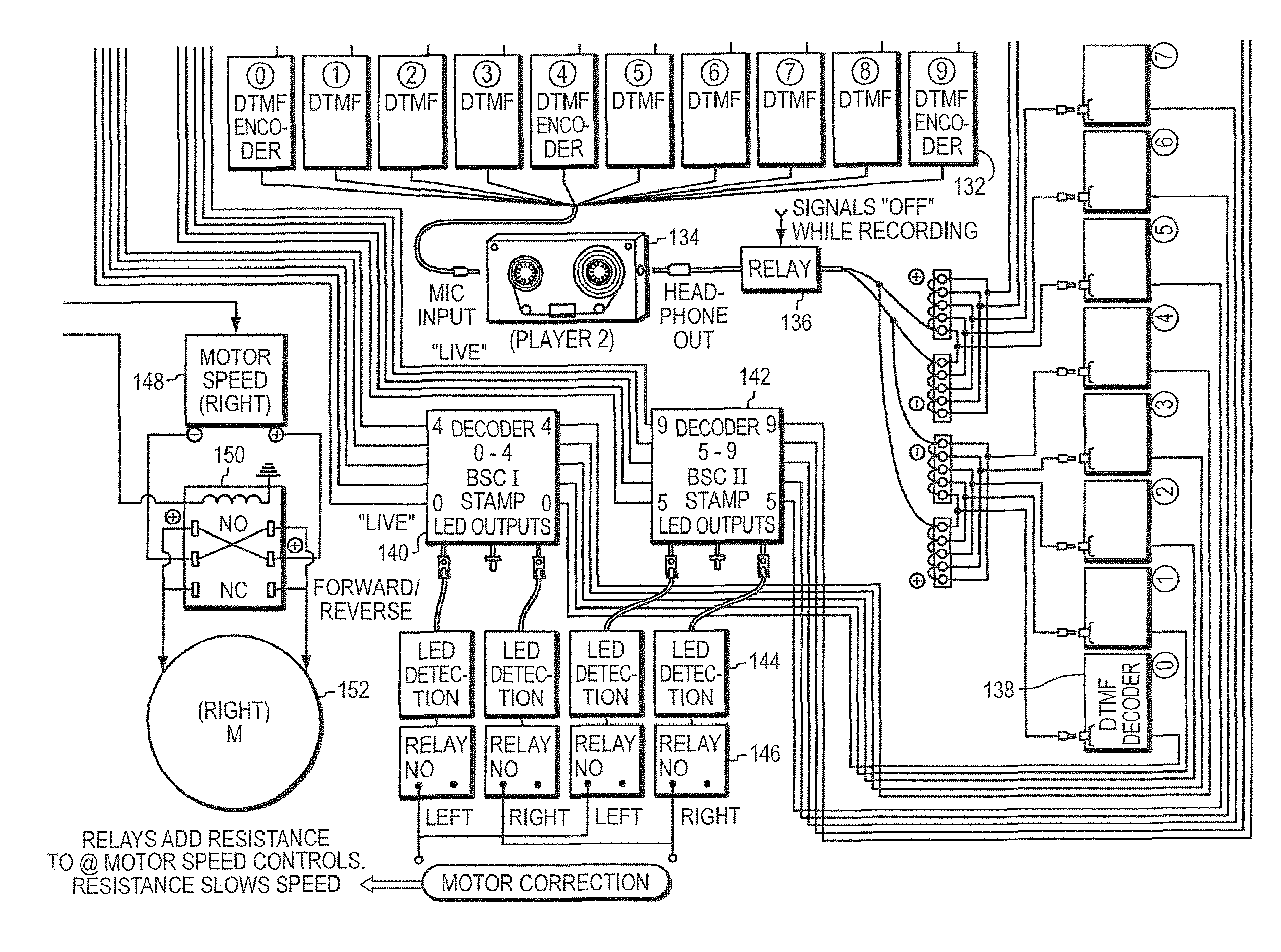
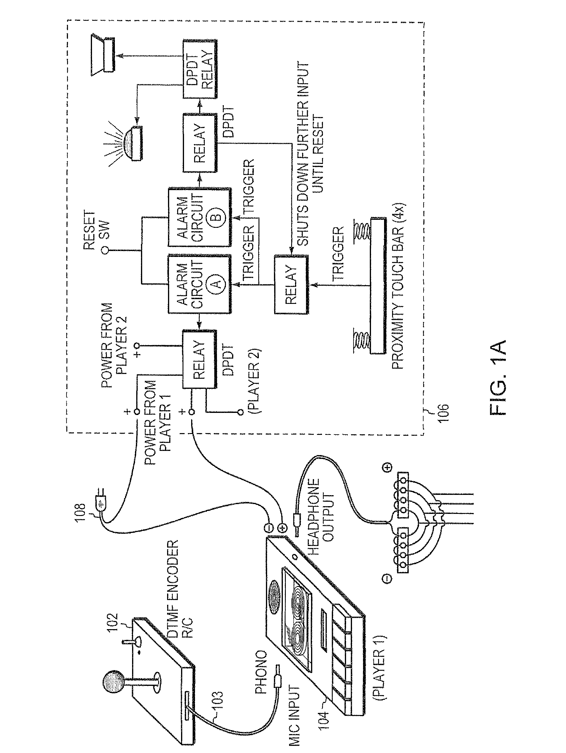
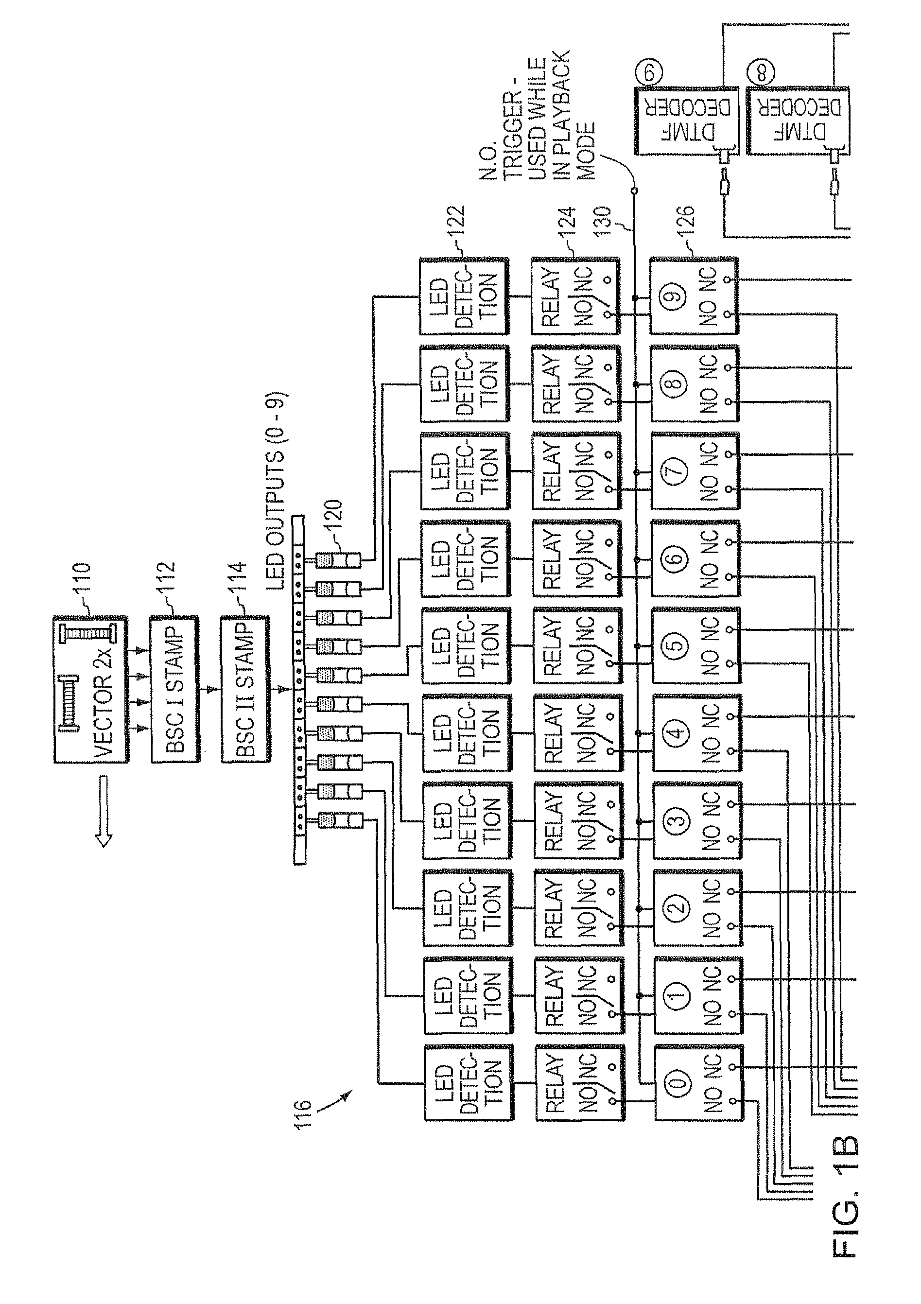
[0036]Robotic apparatus built and operated according to principles of the invention provide systems and methods for operating in an autonomous manner under the control of a programmed computer operating in communication with a digital compass configured to discern an orientation of the robotic apparatus. In one embodiment, the digital compass senses the magnetic field of the planet Earth. The digital compass can be implemented as a device built on a circuit board, which can discriminate two or three axial directions. Orientation readings provided by the compass are used during the operation of the robotic apparatus. An electronic digital compass suitable for use with the present invention is described in U.S. Pat. No. 4,851,775, issued on Jul. 25, 1989 to Kim et al., and assigned to Precision Navigation, Inc. of Menlo Park, Calif., the entire disclosure of which is expressly incorporated herein by reference in its entirety. Electronic digital compasses of this type are available com...


PUM


Abstract

A robotic apparatus for traversing a selected area autonomously that senses orientation relative to “environmental” signals. The robotic apparatus is provided in two models, a master that can record directive and “environmental signal” readings, or that can record received location information, to provide at least one command recorded on a machine-readable medium representing an instruction for traversing an area of interest, and a slave that lacks the recording capability. Both master and slave models can replay recorded commands, and compare the expected orientation from the command with an actual orientation sensed during autonomous operation. If an error exceeding a predetermined value is observed, a corrective action is taken. The robotic apparatus is able to utilize a tool to perform a task.

Description

CROSS-REFERENCE TO RELATED APPLICATIONS[0001]This application is a continuation-in-part of co-pending U.S. patent application Ser. No. 10 / 631,465, filed Jul. 31, 2003, which application is a continuation-in-part of U.S. patent application Ser. No. 10 / 401,266 filed Mar. 27, 2003, issued as U.S. Pat. No. 7,107,132 on Sep. 12, 2006, and this application also claims, through said U.S. patent application Ser. No. 10 / 401,266, priority to and the benefit of U.S. provisional patent application Ser. No. 60 / 368,196, filed Mar. 28, 2002, each of which applications are incorporated herein by reference in its entirety. This application additionally claims the priority and benefit of U.S. provisional patent application Ser. No. 60 / 812,231, filed on Jun. 9, 2006, which application is incorporated herein by reference in its entirety.FIELD OF THE INVENTION[0002]The invention relates to mobile robotic apparatus in general and particularly to a robotic apparatus that comprises programmed instructions ...

Claims


Application Information

Patent Timeline
Patent Type & Authority Patents(United States)
IPC IPC(8): G05D1/00G05D1/02G06F19/00A01D34/00G01C21/00
CPCG01C21/00G05D1/0272G05D1/0259Y10S901/47G05D1/028G05D2201/0209Y10S901/01G05D1/0278
Inventor DEAN, JASON A.
Owner DEAN JASON A
Learn More