Blade holding apparatus

a technology for holding apparatuses and blades, applied in the direction of machine supports, machines/engines, transportation items, etc., can solve the problems of difficult access to the top side of the blade, difficult handling or processing steps, and expensive and time-consuming handling procedures

Active Publication Date: 2015-03-24
SIEMENS GAMESA RENEWABLE ENERGY AS
View PDF24 Cites 8 Cited by
  • Summary
  • Abstract
  • Description
  • Claims
  • Application Information

AI Technical Summary

Benefits of technology

[0009]An advantage of the blade holding apparatus according to the invention is that the blade can be held or supported in a very straightforward manner during handling, and in such a way that only a very small fraction of its surface area is covered by elements of the clamping arrangement, so that most of the blade surface can be accessed for treatment. Furthermore, the force exerted by the clamping arrangement on the surface of the blade is very favourably distributed about the circumference of the blade, so that damage or stress to the blade can be avoided. Since the support structure is realised to hold the blade near one end, for example the tip end, it is only necessary to support the blade at one other end, for example the root end, most of the blade surface is left freely accessible.
[0011]An advantage of the method according to the invention of operating such a blade holding apparatus is that, with a minimum of effort, most of the blade surface can be accessed for treatment. The method according to the invention is favourably safe, since the blade is clamped securely but without having to apply excessive pressure, during the handling procedure. Therefore, the safety of service workers is ensured, and the risk of damage to the blade is essentially eliminated.
[0017]Preferably, the blade holding apparatus comprises a support frame for holding the support structure. Such a support frame can have a suitable bearing so that the support structure can rotate freely, i.e. with a minimum of friction. The support frame can itself be moveable, for example to transport the support structure between locations, and be equipped with wheels for this purpose, and a brake for maintaining its position at a certain location.
[0019]Preferably, a clamping force is applied essentially evenly about the section of the blade that is being supported. To this end, the support structure can comprise one or more blade gripping elements that exert a force on the blade. For example, the tip disc can comprise one blade gripping element mounted on a first side of the opening that acts to press the blade towards the opposite side of the opening. In such an embodiment, the opening is preferably shaped to suit the contour at that section of the blade. However, such a realisation might result in an uneven distribution of forces over the surface of the blade, so that damage to the blade surface might arise. Therefore, in a preferred embodiment of the invention, the clamping arrangement comprises a pair of blade gripping elements or “jaws” mounted one on each side of the opening in the support structure. Such a realisation, in which the clamping force is applied on both front and back surfaces of the blade, can provide a favourable distribution of forces and can avoid any damage to the blade surface.
[0022]In a particularly preferred embodiment of the invention, the clamping arrangement comprises a flexible connecting means for connecting the blade gripping elements such that a downward force exerted on the connecting means results in a downward motion of a blade gripping element. For example, such a flexible connecting means can comprise a strap suspended between lower points on the blade gripping elements. An outer edge of the blade can rest on the strap, so that, when the weight of the blade rests on the strap, a downward movement and a corresponding lateral movement of one or both blade gripping elements is effected, so that a distance between the blade gripping elements is reduced, thereby effectively exerting a clamping force on the blade. Preferably, the blade is inserted into the clamping arrangement such that a leading edge of the blade is pointing downwards. In this way, the rounded leading edge rests on the strap, and the narrow trailing edge points upwards.
[0025]Preferably, the locking arrangement comprises a position-locking means for locking a position of the ratchet, so that the ratchets are fixed in place, for example during a rotation of the support structure. To this end, the locking arrangement comprises some suitable blocking means that blocks the spring, i.e. a means that prevents the spring from compressing and therefore prevents a lateral movement of the second ratchet row. By allowing the clamping arrangement to be locked in position in this manner, the blade can be held securely by the clamping arrangement even when the support structure is rotated during the handling procedure.

Problems solved by technology

However, such a handling or processing steps can be problematic since rotor blades are becoming longer as advances in turbine design and blade manufacture allow for larger generators and larger rotor blade lengths.
The differently shaped zones along the length of the blade, together with the weight of the blade and the care that must be taken to avoid any damage to the blade surface, result in expensive and time-consuming handling procedures.
However, the top side of the blade can only be accessed with difficulty.
Either way, the prior art techniques are time-consuming and therefore also expensive.
Furthermore, the use of such a screw mechanism can result in damage to those regions of the blade about which it is clamped.
Also, the securing of the screw mechanism relies exclusively on the manpower of the operator, so that a secure fastening cannot always be guaranteed.

Method used


Image

  • Blade holding apparatus
  • Blade holding apparatus
  • Blade holding apparatus

Examples


Embodiment Construction

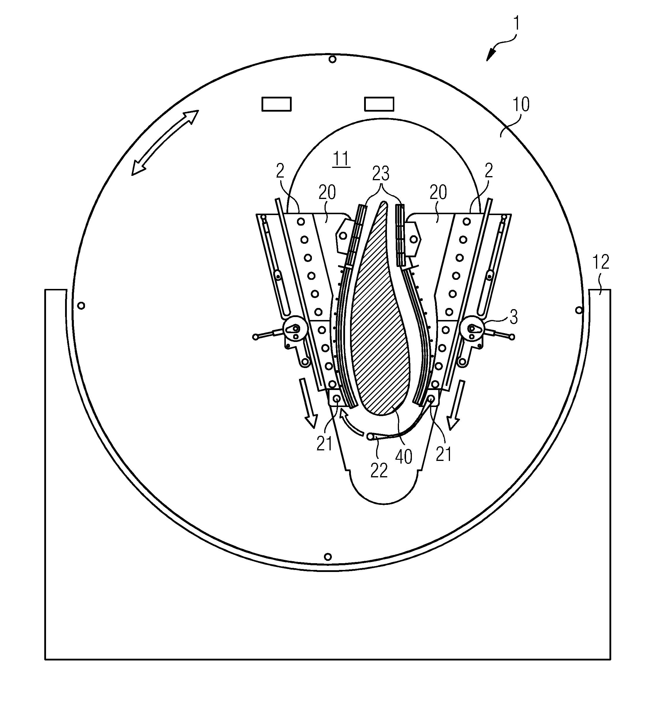
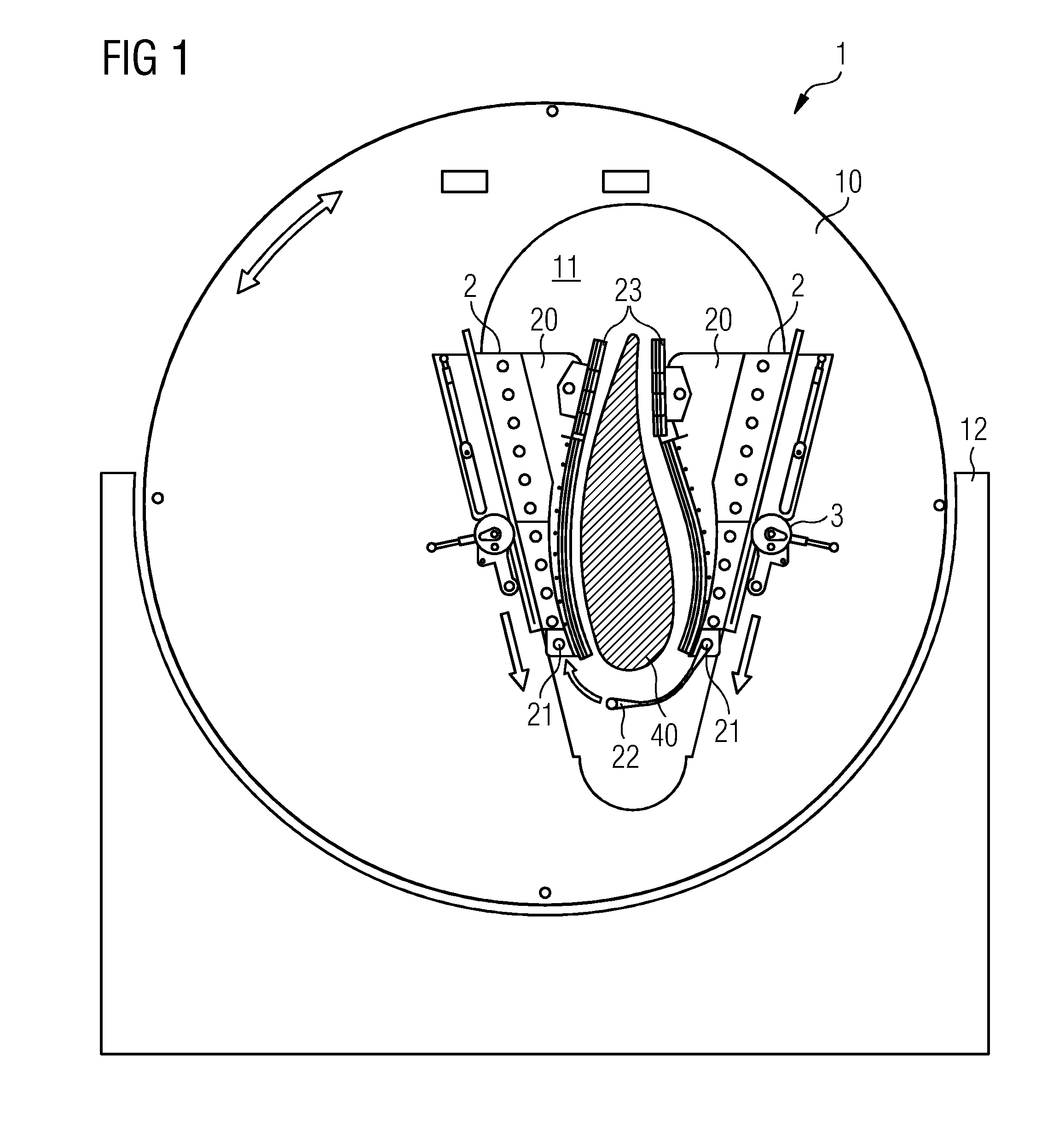
[0034]FIG. 1 shows a blade holding apparatus 1 according to an embodiment of the invention in an initial unloaded position. The diagram shows a frontal view of the blade holding apparatus 1, and shows a vertical support structure 10 or tip disc 10 mounted on a support frame 12. The tip disc 10 is rotatable in this realisation about its geometrical centre, as indicated by the curved arrow. An opening 11 is dimensioned to accommodate elements 2, 20 of a clamping arrangement. In this embodiment, the clamping arrangement comprises a pair of blade gripping elements 2, each mounted to a rigid base 20. The blade gripping elements 2 are connected by means of a removable strap 22, which is hooked onto a short pin 21 or trunnion 21. The clamping arrangement is realised to interact with a locking arrangement. To this end, the rigid base 20 of a blade gripping element 2 comprises a first row of teeth for a ratchet, and a corresponding second row of teeth is mounted on the support structure 10, ...


PUM


Abstract

A blade holding apparatus for holding one end of a wind turbine blade during handling, which blade holding apparatus includes a support structure including an opening for accommodating one end of the wind turbine blade, a clamping arrangement arranged in the opening, which clamping arrangement is realized to exert a clamping force on the wind turbine blade, and a locking arrangement for locking the clamping arrangement relative to the support structure. A method of operating such a blade holding apparatus during a handling procedure of a wind turbine blade is also provided.

Description

CROSS REFERENCE TO RELATED APPLICATIONS[0001]The present application claims priority to European Patent Office application No. 12170530.5 EP filed Jun. 1, 2012, the entire content of which is hereby incorporated herein by reference.FIELD OF INVENTION[0002]The invention describes a blade holding apparatus and a method of operating such a blade holding apparatus.BACKGROUND OF INVENTION[0003]Rotor blades for a wind turbine must be finished according to certain criteria. For example, the outer surface of the rotor blade must be smooth, so that the aerodynamic properties of the rotor are not compromised. Furthermore, the surface of the rotor blade should be weather resistant. For these reasons, the surface of rotor blade must generally undergo one or more handling or processing steps such as sanding, painting, polishing, etc., before being transported to the site for mounting onto a wind turbine.[0004]However, such a handling or processing steps can be problematic since rotor blades are ...

Claims


Application Information

Patent Timeline
Patent Type & Authority Patents(United States)
IPC IPC(8): B60P3/40F03D1/00F16M11/04
CPCF16M11/04F03D1/005Y02E10/72F03D13/40
Inventor BITSCH, MICHAEL BRIXKNUDSEN, PETERPEDERSEN, DAVID STIENTALEBNASAB, REZAUHRENHOLT, JESPER
Owner SIEMENS GAMESA RENEWABLE ENERGY AS
Why Eureka
Try Eureka