Lithographic apparatus and device manufacturing method

a technology of lithographic equipment and manufacturing method, which is applied in the direction of photomechanical exposure equipment, printing equipment, instruments, etc., can solve the problems of easy instability of the control system, increased gain of the transfer function of the system, and movement of the projection system, so as to increase achieve stable control system. , the effect of increasing the bandwidth of the control system

Inactive Publication Date: 2015-03-31
ASML NETHERLANDS BV
View PDF17 Cites 2 Cited by
  • Summary
  • Abstract
  • Description
  • Claims
  • Application Information

AI Technical Summary

Problems solved by technology

However due to vibrations and other movements in the lithographic apparatus, movements of the projection system may occur.
A drawback of the known embodiment is that the control system may easily become unstable as for higher frequencies the gain of the transfer function of the system may increase while the phase crosses −180 degrees.
The combination of high or even increasing gains for high frequencies increases the risk on an unstable system.
However, for the above-described known active damping system the application of such a first of higher order low-pass filter may not be possible since the damping of the gains also implies a phase lag, therewith generally decreasing the frequency at which −180 degrees is crossed and increasing the chance on instability.
As a result, it may be difficult or even impossible to position the cut-off frequency of the first or higher order filter such that a stable system is obtained.

Method used


Image

  • Lithographic apparatus and device manufacturing method
  • Lithographic apparatus and device manufacturing method
  • Lithographic apparatus and device manufacturing method

Examples


Embodiment Construction

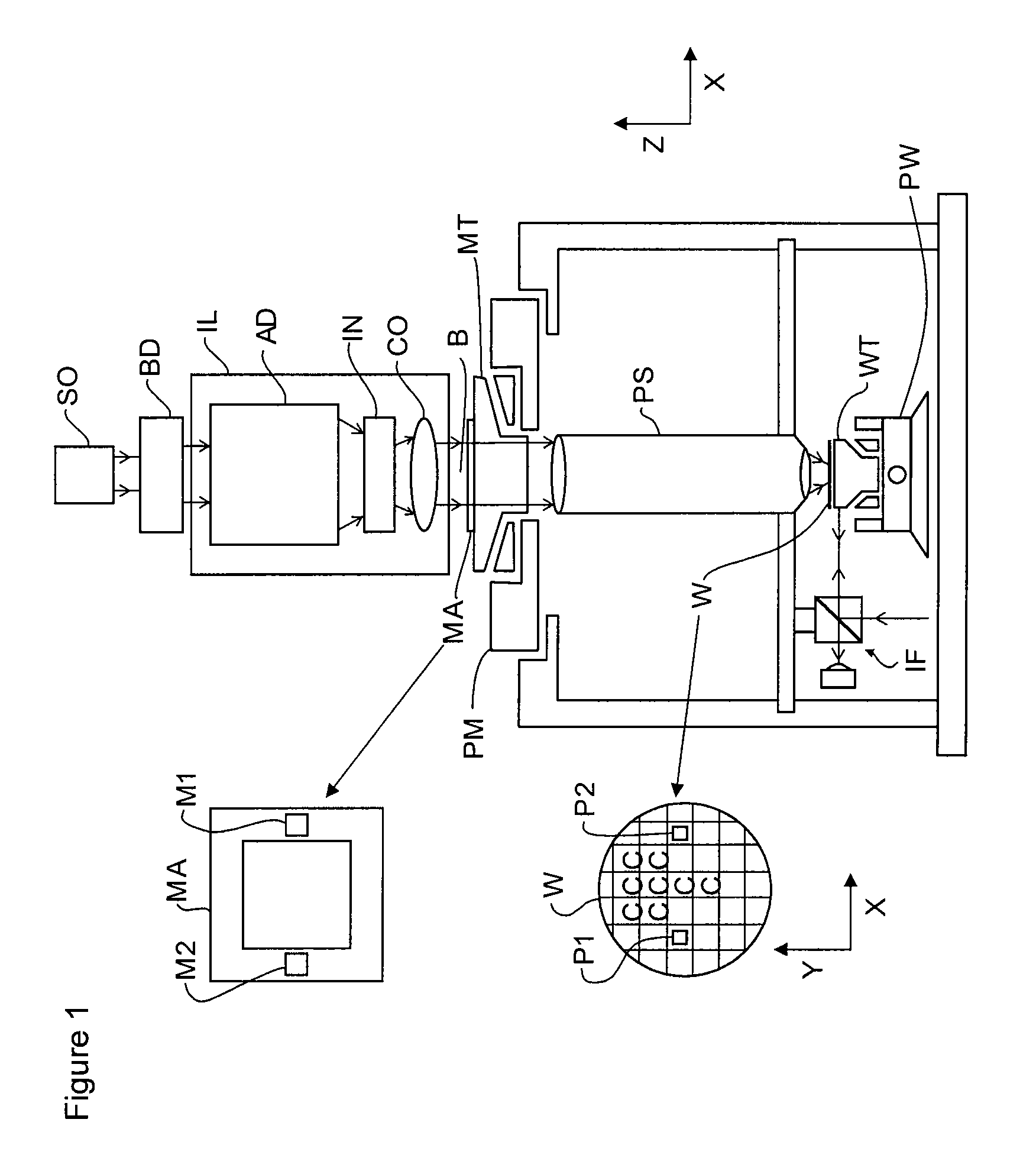
[0027]FIG. 1 schematically depicts a lithographic apparatus according to one embodiment of the invention. The apparatus includes an illumination system (illuminator) IL configured to condition a radiation beam B (e.g. UV radiation or any other suitable radiation), a support structure or pattern support or support (e.g. a mask table) MT constructed to support a patterning device (e.g. a mask) MA and connected to a first positioning device PM configured to accurately position the patterning device in accordance with certain parameters. The apparatus also includes a substrate table (e.g. a wafer table) WT or “substrate support” constructed to hold a substrate (e.g. a resist-coated wafer) W and connected to a second positioning device PW configured to accurately position the substrate in accordance with certain parameters. The apparatus further includes a projection system (e.g. a refractive projection lens system) PS configured to project a pattern imparted to the radiation beam B by p...


PUM

PropertyMeasurementUnit
center frequencyaaaaaaaaaa
cutoff frequencyaaaaaaaaaa

Abstract

A control system for controlling a position or position related quantity of an object is provided. A measurement system is configured to measure a position or position related quantity of the object. A controller is configured to provide a control signal on the basis of the measured position or position related quantity. A actuator actuates the object on the basis of the control signal. A filter unit, which may be a partial order filter unit, filters the measured position or position related quantity.

Description

CROSS-REFERENCE TO RELATED APPLICATION[0001]This application claims the benefit of the filing date of U.S. provisional application 60 / 960,514, filed on Oct. 2, 2007. The subject matter of the provisional application is incorporated herein by reference as if fully set forth herein.BACKGROUND OF THE INVENTION[0002]1. Field of the Invention[0003]The present invention relates to a control system to control a position or position related quantity such as velocity or acceleration of an object, a lithographic apparatus including a control system and a method for increasing the bandwidth of a position control system.[0004]2. Background Art[0005]A lithographic apparatus is a machine that applies a desired pattern onto a substrate, usually onto a target portion of the substrate. A lithographic apparatus can be used, for example, in the manufacture of integrated circuits (ICs). In such a case, a patterning device, which is alternatively referred to as a mask or a reticle, may be used to genera...

Claims


Application Information

Patent Timeline
Patent Type & Authority Patents(United States)
IPC IPC(8): G03B27/42G03F7/20G05D19/02
CPCG03F7/70775G03F7/709G05D19/02
Inventor BUTLER, HANSVAN DER WIJST, MARC WILHELMUS MARIADE HOON, CORNELIUS ADRIANUS LAMBERTUS
Owner ASML NETHERLANDS BV
Why Eureka
Try Eureka