Structure for mounting heat sink, and heat sink mounted using the structure

a technology for mounting structures and heat sinks, which is applied in the direction of electrical apparatus casings/cabinets/drawers, instruments, and semiconductor/solid-state device details, etc., can solve the problems of difficult work for forming the slit-like openings shown in fig. 17(a)/i>a), and achieve the effect of preventing the anchor from falling off, ensuring the mounting of the heat sink, and effective utilization of the circuit board surfa

Active Publication Date: 2015-03-31
KATAOKA TETABUJI +1
View PDF31 Cites 7 Cited by
  • Summary
  • Abstract
  • Description
  • Claims
  • Application Information

AI Technical Summary

Benefits of technology

[0038]The problems are solved by means of the configurations of the invention disclosed herein.
[0039]According to the invention, in the structure, the main body section of the anchor is formed in the substantially circular shape or the regular prism shape in plan view and the spring member is fastened to the anchor in an externally fit state (directly or indirectly). Therefore, it is possible to form the anchor (the main body section) extremely small, a setting space for providing the anchor only has to be a very small area, and effective utilization of a circuit board surface can be attained.
[0040]According to the invention, in the anchor, the base section and the main body section are integrally formed and the attaching section and the main body section are integrally formed. Therefore, for example, after the heat sink body is positioned, it is unnecessary to attach a member larger than the main body section to an anchor head to form the attaching section. After the positioning, it is possible to immediately operate the spring member to mount the heat sink body.
[0041]According to the invention, the anchor (the main body section) is formed in the substantially columnar shape having the maximum diameter of about 1.7 mm. Therefore, an attachment hole formed on the circuit board in order to fixedly set the anchor only has to have a very small hole size of about 1.7 mm. Therefore, a lost area and a lost shape on the circuit board involved in the setting of the anchor is suppressed to a circle having a diameter of about 1.7 mm or a square having the length of one side of about 1.7 mm (strictly, a brim-like flange section is also included in the lost area). The lost area is extremely small.
[0042]Note that the size and the setting area of the anchor are not such a very small size (a large size) in the past. This is considered to be because there is no way of fastening a wire spring in an externally fitting form. In a mounting method in the past, the wire spring is hooked to the anchor having the substantially U shape as explained above. Therefore, an area having a relatively elongated shape is indispensable to provide the anchors. On the other hand, in another mounting method such as push pins, a shape for providing anchors is not an elongated shape (area) and only has to be a circular shape. However, because the tips of the push pins are elastically deformed and attached, a certain degree or larger size (hole diameter) is necessary. Therefore, there is no idea of forming the anchors in a very small size.
[0043]According to the invention, the anchor including the flange formed in the base section is fit in (pres-fit) from the substrate rear surface and set. Therefore, when the heat sink is mounted, a tensile force (a pullout force) in a fitting direction acts on the anchor according to the elasticity of the spring member. However, the flange assumes an action of slip-off prevention. Therefore, it is possible to prevent the anchor from slipping off. Further, this contributes to sure mounting of the heat sink.

Problems solved by technology

Therefore, in both cases, as a result, a relatively large range including the elongated areas on the circuit board B cannot be used for a circuit.
Consequently, although the areas are secured to set the anchors 5′, the increase in the areas that cannot be used as a circuit is a significant factor of influence and limitation on circuit design.
Further, for example, work for forming the slit-like openings shown in FIG. 17(a) on the circuit board B is difficult work compared with work for opening circular holes.

Method used


Image

  • Structure for mounting heat sink, and heat sink mounted using the structure
  • Structure for mounting heat sink, and heat sink mounted using the structure
  • Structure for mounting heat sink, and heat sink mounted using the structure

Examples


first embodiment

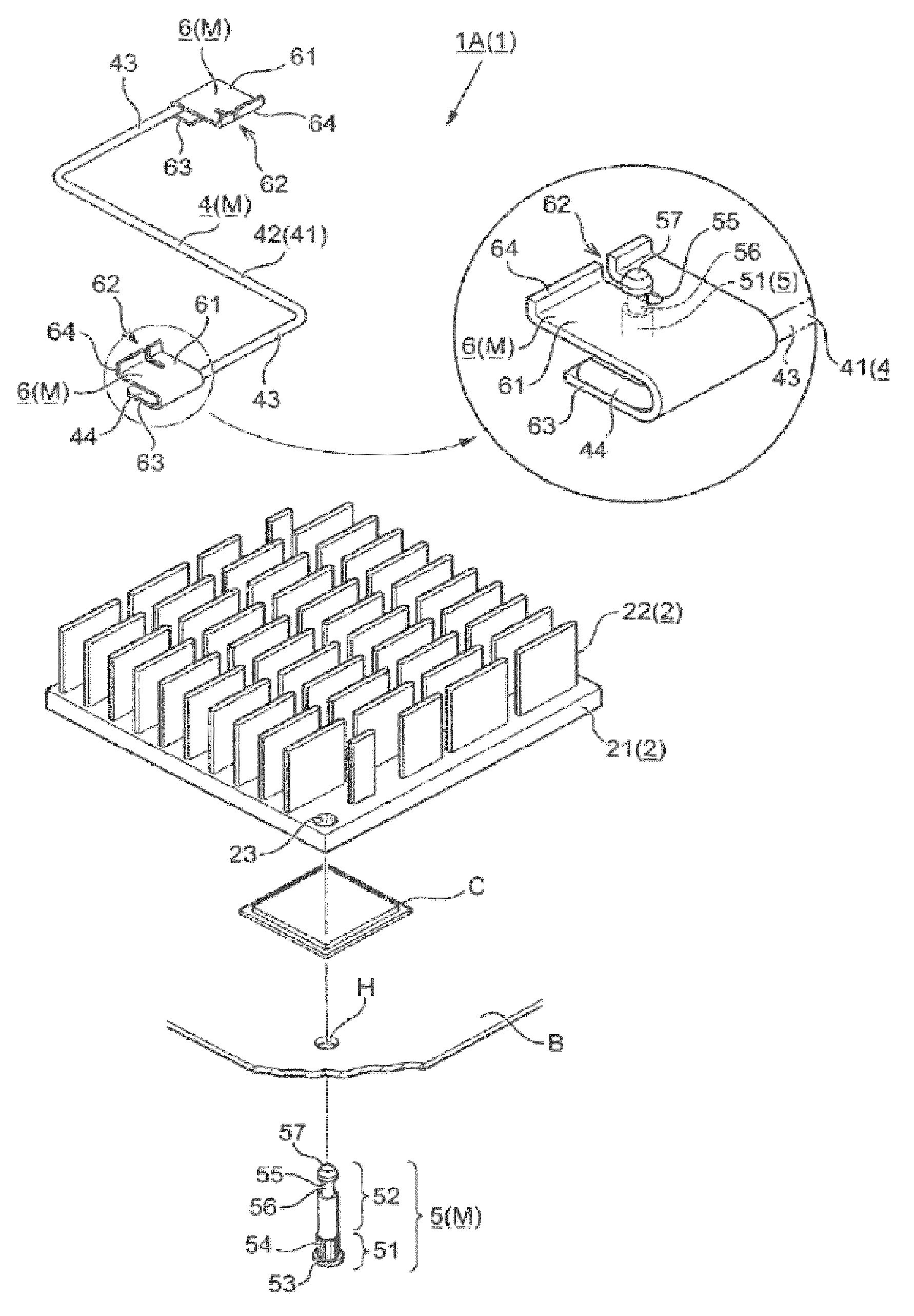
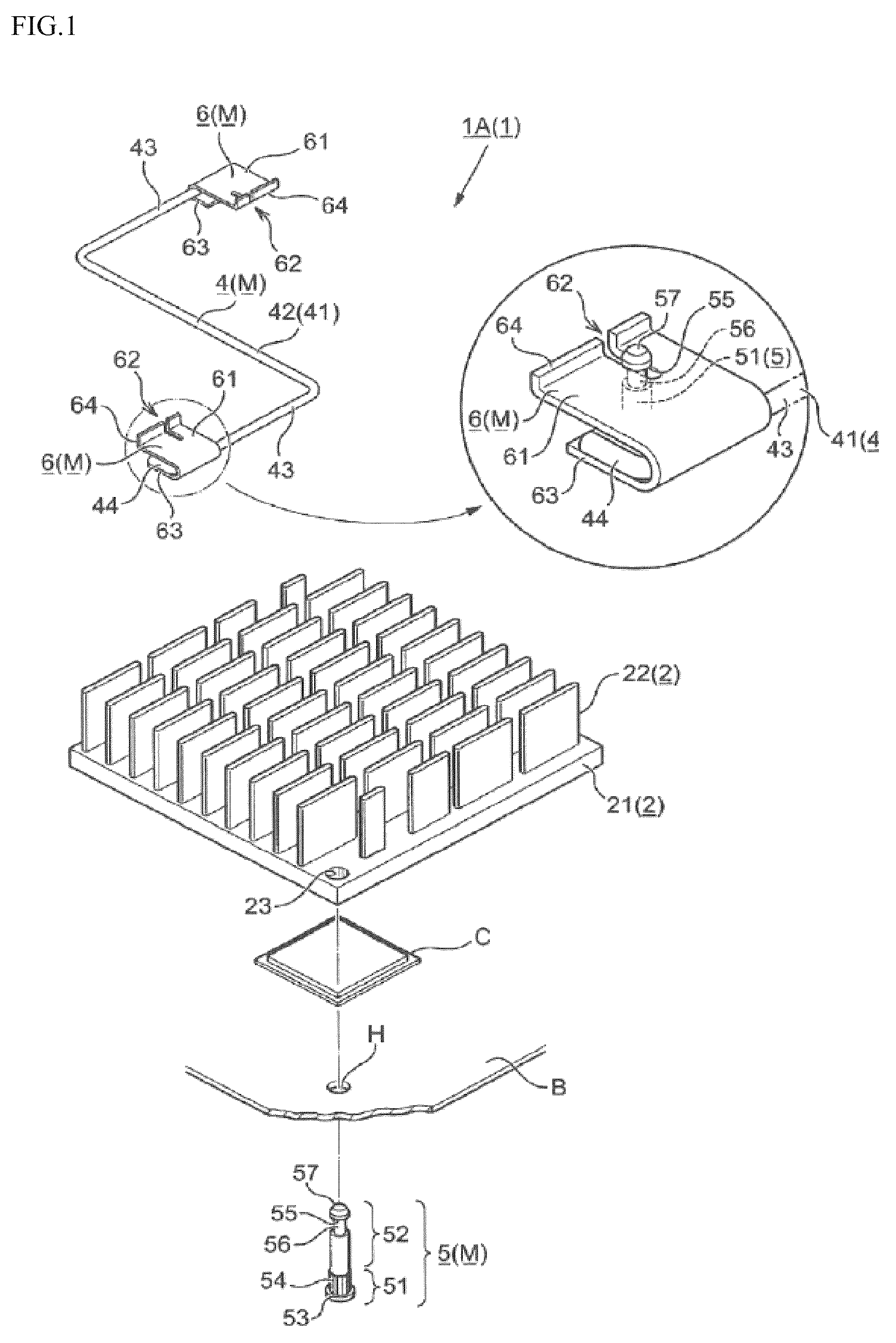
[0073]As a basic form of the heat sink 1 (1A) in a first embodiment, the attachment pieces 6 are formed separately from the wire spring 41 and the attachment pieces 6 and the wire spring 41 are joined by welding or the like later. The heat sink 1A in the first embodiment mainly includes, as shown in FIG. 1 as an example, a heat sink body 2 that performs heat radiating action and mounting means M for mounting the heat sink body 2 on the circuit board B. These members are explained below.

[0074]The heat sink body 2 is formed of a material excellent in thermal conductivity and heat radiation properties such as aluminum. The heat sink body 2 has a basis structure in which a large number of heat radiation fins 22 are formed to be projected from a tabular base 21.

[0075]In the base 21, a surface on which the heat radiation fins 22 are not formed is a contact surface that is compression-bonded (closely attached) to the semiconductor circuit elements C. In general, a thermal conductive sheet ...

second embodiment

[0111]Next, the heat sink 1 (1B) in a second embodiment is explained.

[0112]The heat sink 1B in the second embodiment basically follows the structure of the first embodiment. However, the heat sink 1B is different in points explained below. In the first embodiment, the attachment pieces 6 are provided in the fixed state with respect to the wire spring 41. However, in the second embodiment, the attachment pieces 6 are provided in a movable state with respect to the wire spring 41. The attachment pieces 6 are provided in the movable state with respect to the wire spring 41 in this embodiment because of consideration (intension) that a movable range further expands (a degree of freedom of movability increases) according to the movement of the attachment pieces 6 (movability with respect to the wire spring 41) in addition to the movement due to bending, twisting, and the like by the wire spring 41 and the mounting work can be more surely and more easily performed.

[0113]Examples of such a...

third embodiment

[0120]Next, the heat sink 1 (1C) in a third embodiment is explained.

[0121]The heat sink 1C in the third embodiment includes, as shown in FIG. 8(a) as an example, the attachment pieces 6 of a push nut type. The attachment pieces 6 are forcibly fit in the attaching sections 55 (the anchor heads) of the anchors 5 to mount the heat sink body 2. The attachment pieces 6 of the push nut type in this embodiment are different from the embodiments 1 and 2 in the structure and a mounting form (a fitting form) of the attachment pieces 6. Therefore, the attachment pieces 6 are hereinafter referred to as “attachment pieces 6C” following the end sign of the heat sink 1C.

[0122]In the attachment pieces 6C in this embodiment, because of the structure explained above, insertion holes 71 fit over the attaching sections 55 of the anchors 5 therein are formed. Returns 72 having a reverse claw shape are formed on both sides of the insertion holes 71. To obtain the mounted state, the insertion holes 71 of ...


PUM


Abstract

A new mounting structure is provided in which, when a heat sink is mounted (fixed) on a circuit board using a spring member, an anchor for fixing the spring member is formed in a very small size in plan view. In the present invention, at least one anchor for mounting a heat sink body on a circuit board is set in a projected state on the heat sink body side and both ends of a spring member are each directly or indirectly attached to an anchor, whereby the heat sink body is mounted on the circuit board. In the anchor, a main body section projecting on the circuit board is formed in a substantially circular shape or a polygonal shape. When the spring member is attached to the anchor, the spring member is attached to an attaching section in an externally fit state.

Description

RELATED APPLICATIONS[0001]The application is a U.S. national phase under 35 U.S.C. §371 of International Application No. PCT / JP2011 / 063387 filed Jun. 10, 2011, claiming priority of Japanese Application No. 2010-139139 filed Jun. 18, 2010.TECHNICAL FIELD[0002]The present invention relates to a heat sink for efficiently discharging heat emitted from an electronic component (a semiconductor circuit element) of a microprocessor, an inverter, or the like and, more particularly, to a new mounting structure in which, when the heat sink is mounted on a circuit board using a spring member, an anchor for fixing (hooking) the spring member is formed in a very small size in plan view and a setting area of the anchor is minimized to enable a circuit board area to be extremely effectively utilized.BACKGROUND ART[0003]A semiconductor circuit element mounted (loaded) on a circuit board generates heat according to the operation of an electronic device. Therefore, in order to efficiently discharge th...

Claims


Application Information

Patent Timeline
Patent Type & Authority Patents(United States)
IPC IPC(8): H05K7/20G06F1/20H01L23/40
CPCH01L23/4093H01L23/4006H01L2924/0002H01L2924/00Y10T24/308Y10T24/44026
Inventor KATAOKA, TETSUJIKATAOKA, TAIJIROU
Owner KATAOKA TETABUJI
Why Eureka
Try Eureka