Supercharge Your Innovation With Domain-Expert AI Agents!

Manufacturing method for toothed member, manufacturing device for toothed member, and toothed member

a manufacturing device and toothed member technology, applied in the direction of forging/pressing/hammering equipment, forging tools, hoisting equipment, etc., can solve the problems of reducing reducing the strength of the constraint punch, and reducing the strength so as to prevent the material from turning and improve the durability of the toothed member

Active Publication Date: 2015-04-07
AISIN AW CO LTD
View PDF37 Cites 0 Cited by
  • Summary
  • Abstract
  • Description
  • Claims
  • Application Information

AI Technical Summary

Benefits of technology

This approach effectively prevents material turning and enhances the durability of the toothed member by maintaining the restraint die's contact with the bottom surface, preventing material flow and allowing for the formation of a toothed member with improved strength and reduced material trapping, thus improving the manufacturing process and the quality of the final product.

Problems solved by technology

However, the urging force of a spring is not enough to apply a sufficient load to the restraint punch, and thus the restraint punch may not apply a sufficient load to the raw material.
The trapped material 210 reduces the strength, and therefore reduces the durability of the toothed member.

Method used


Image

  • Manufacturing method for toothed member, manufacturing device for toothed member, and toothed member
  • Manufacturing method for toothed member, manufacturing device for toothed member, and toothed member
  • Manufacturing method for toothed member, manufacturing device for toothed member, and toothed member

Examples


first embodiment

Configuration of Manufacturing Device

[0061]First, the configuration of a manufacturing device 1 for a toothed member according to a first embodiment will be described. The manufacturing device 1 for a toothed member processes a workpiece 10 which is a flat disk-shaped raw material to manufacture a toothed member 12 (see FIG. 22).

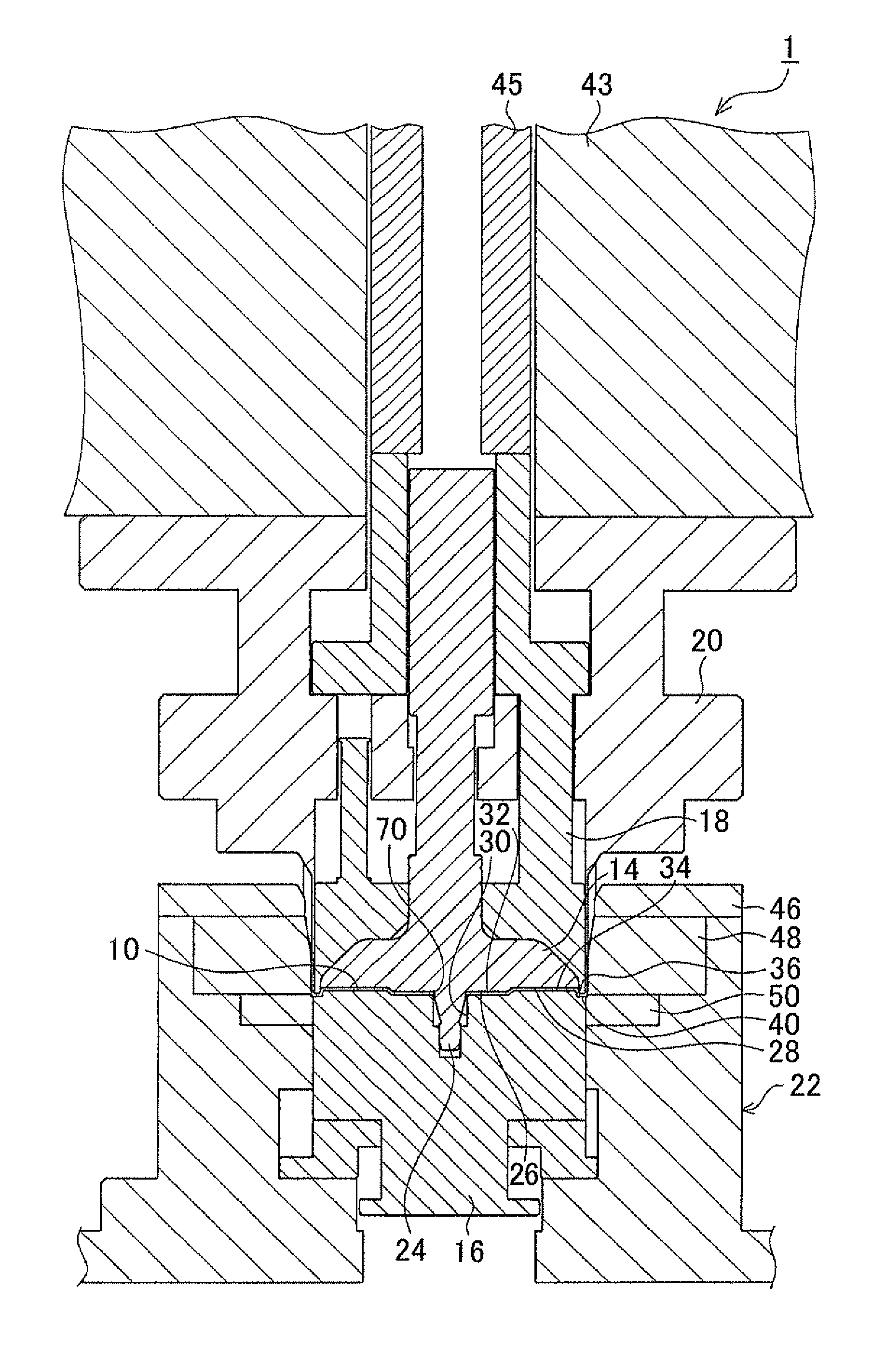
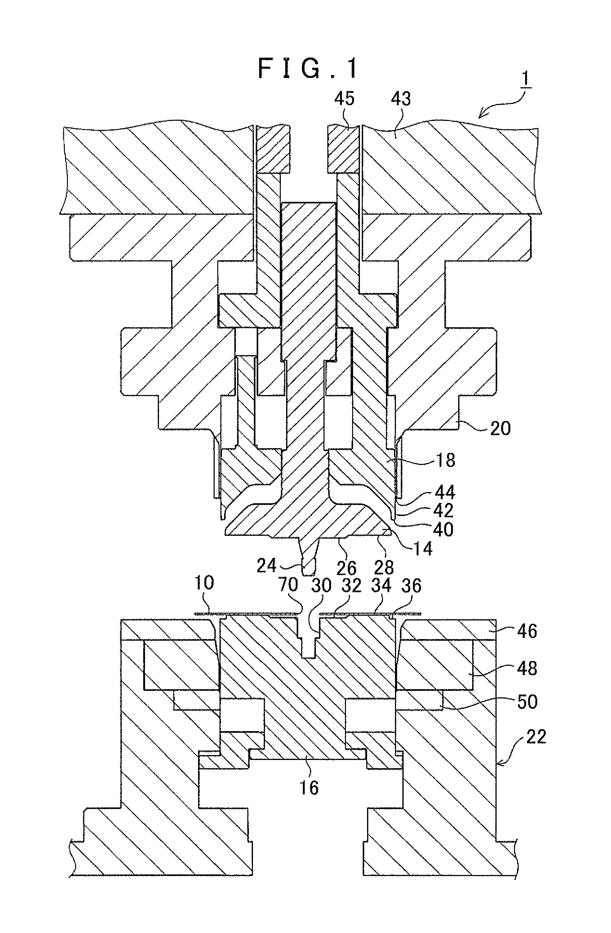
[0062]FIG. 1 shows the overall configuration of the manufacturing device 1 for a toothed member according to the first embodiment. FIG. 1 shows a state in a workpiece placement process to be discussed later. As shown in FIG. 1, the manufacturing device 1 for a toothed member includes a first restraint punch 14, a second restraint punch 16, a toothed punch 18, a compression punch 20, and a die portion 22.

[0063]The first restraint punch 14 is disposed at a position at which it faces the second restraint punch 16 (at a position in the upper direction of FIG. 1). A surface of the first restraint punch 14 facing the second restraint punch 16 is formed to have a c...

second embodiment

[0108]Next, a second embodiment will be described. In the following description, constituent elements that are equivalent to those according to the first embodiment are denoted by the same reference numerals so that the same description will not be repeated, and differences will be focused on. In the second embodiment, a manufacturing device 2 shown in FIG. 26 is used to perform a thickened tooth shaping process. More specifically, the workpiece placement process to the reduced-diameter tooth shaping process are performed on the workpiece 10, and the workpiece 10 after the reduced-diameter tooth shaping process is placed on the manufacturing device 2 to be subjected to the thickened tooth shaping process. As shown in FIG. 26, the manufacturing device 2 includes a restraint punch 96, a pressure receiving member 98, a compression punch 100, a die portion 102, and so forth. The restraint punch 96 includes a restraint surface 103 that restrains the bottom surface portion (the first port...


PUM


Abstract

A manufacturing method for a toothed member includes a thickened tooth shaping process in which a toothed shape is formed on a side wall portion while making a thickness of the side wall portion larger than a thickness of a bottom surface portion by relatively moving the compression die with respect to the restraint die and the pressure receiving member in the axial direction from the side of the opening end of the cup-shaped raw material toward the bottom surface portion. The manufacturing method being such that the thickened tooth shaping process includes applying a load against the restraint die such that the restraint die restrains the first surface and the second surface.

Description

INCORPORATION BY REFERENCE[0001]The disclosure of Japanese Patent Application No. 2011-066337 filed on Mar. 24, 2011 and Japanese Patent Application No. 2011-066340 filed on Mar. 24, 2011 including the specification, drawings and abstract is incorporated herein by reference in its entirety.BACKGROUND OF THE INVENTION[0002]The present invention relates to a manufacturing method for a toothed member including a bottom surface portion and a side wall portion in a cylindrical shape provided to extend upright in the axial direction from an outer peripheral end portion of the bottom surface portion and formed with teeth, to a manufacturing device for the toothed member, and to the toothed member.DESCRIPTION OF THE RELATED ART[0003]Japanese Patent No. 2885266 describes a manufacturing method for a toothed member that includes press shaping in which draw shaping is performed on a raw material in a flat plate shape to form a cylindrical side wall portion around the main body of the raw mater...

Claims


Application Information

Patent Timeline
Patent Type & Authority Patents(United States)
IPC IPC(8): B21D53/28B23P15/14B21D22/02B21D37/10B21K1/30F16H55/17
CPCB21D22/02B21D53/28B21D37/10F16H55/17B21K1/30Y10T74/1987Y10T29/49474Y10T29/49472Y10T29/49476Y10T29/49478B21D22/30
Inventor IWATA, DAISUKEHORI, TOMOYUKIYOKOYAMA, NAOKISHIBATA, HIROSHIMAKI, MASAYUKI
Owner AISIN AW CO LTD
Features
  • R&D
  • Intellectual Property
  • Life Sciences
  • Materials
  • Tech Scout
  • Unparalleled Data Quality
  • Higher Quality Content
  • 60% Fewer Hallucinations
Learn More