Frit for high pressure liquid chromatography

a liquid chromatography and high-pressure technology, applied in the field of filters, can solve the problems of insufficient retention of particles less than 2.5 microns in diameter of filters, inability to achieve complete particle retention using conventional frits, and inability to guarantee retention under a given set of conditions, etc., to achieve the effect of improving part strength

Active Publication Date: 2015-04-07
WATERS TECH CORP
View PDF23 Cites 0 Cited by
  • Summary
  • Abstract
  • Description
  • Claims
  • Application Information

AI Technical Summary

Benefits of technology

[0022]According to the subject invention, the frit includes a porous support structure having a plurality of void spaces, the void spaces being filled with a plurality of secondary particles, such that the frit has a density of at least 50%. In other words, the porous support structure and secondary particles make up at least 50% by volume of the frit, whereby the frit forms a highly dense structure (greater than 50% dense). The highly dense structure of the frit enhances part strength and allows the frit to be press fit into cavities or columns without damaging the frit. In certain embodiments, the void spaces are filled with the secondary particles such that the depth of penetration in the frit by the secondary particles is greater than about 10 microns, more preferably ranging from about 28 microns to about 178 microns.

Problems solved by technology

Although such porous filters are capable of retaining particles as small as 2.5 micrometers in diameter under HPLC conditions, these filters have difficulty adequately retaining particles less than 2.5 microns in diameter.
Retention under a given set of conditions does not guarantee retention under various conditions encountered in HPLC.
Therefore, under the desired use conditions, complete particle retention is not achieved using conventional frits.
Conventional frits do not adequately retain sub-2.5 micrometer packings.
Sintering powders of sub-10 micrometer particulate size and of a spherical shape is difficult.
The difficulty in handling compressed forms made from <10 micrometer spherical particle size powders is due to poor mechanical strength of the “green” form prior to sintering.
The poor mechanical strength makes the green forms too unstable to withstand the handling and transfer required in the sintering process.
In addition, green forms produced by compacting <10 micron spherical powders tend to shrink excessively upon sintering, resulting in the formation of cracks and channels in the final frit structure.
However, this solution has the disadvantage of decreasing porosity and hence reducing permeability of the frit.
Alternatively, smaller particle size powders can be used, but such powders suffer from poor “green” strength and excessive shrinkage during sintering.

Method used


Image

  • Frit for high pressure liquid chromatography
  • Frit for high pressure liquid chromatography
  • Frit for high pressure liquid chromatography

Examples


example 1

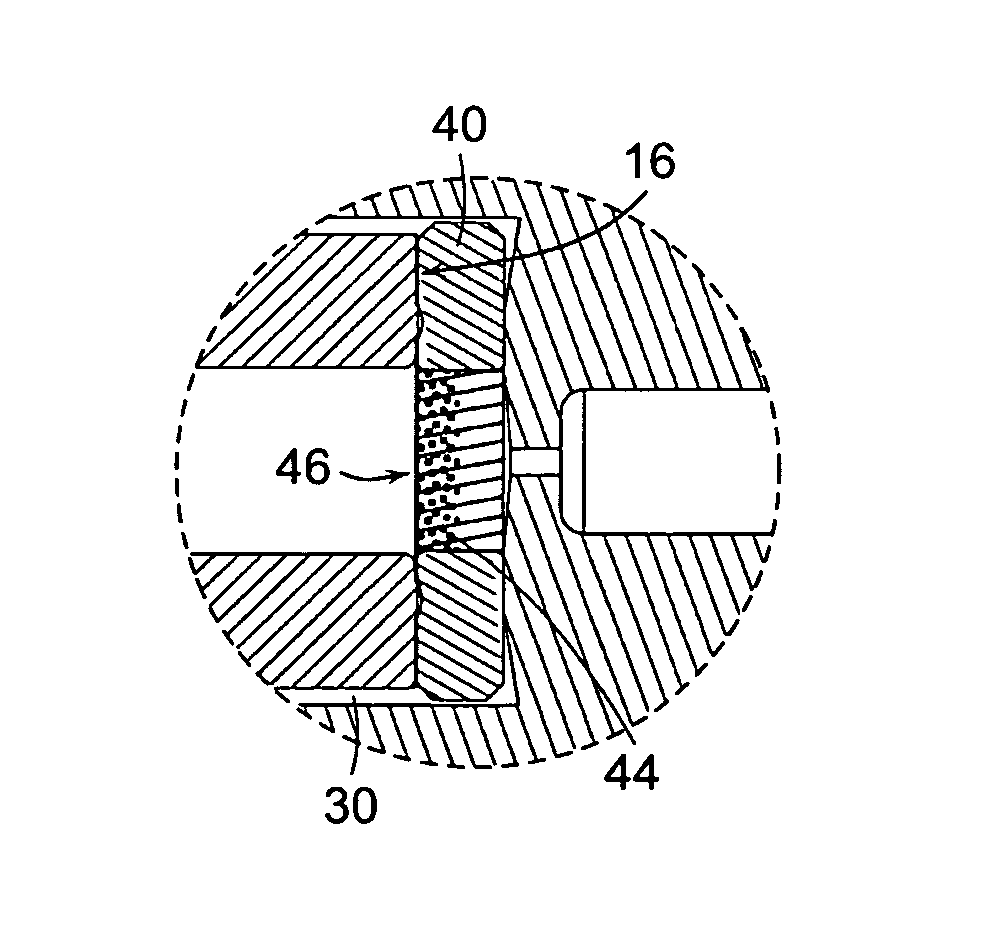
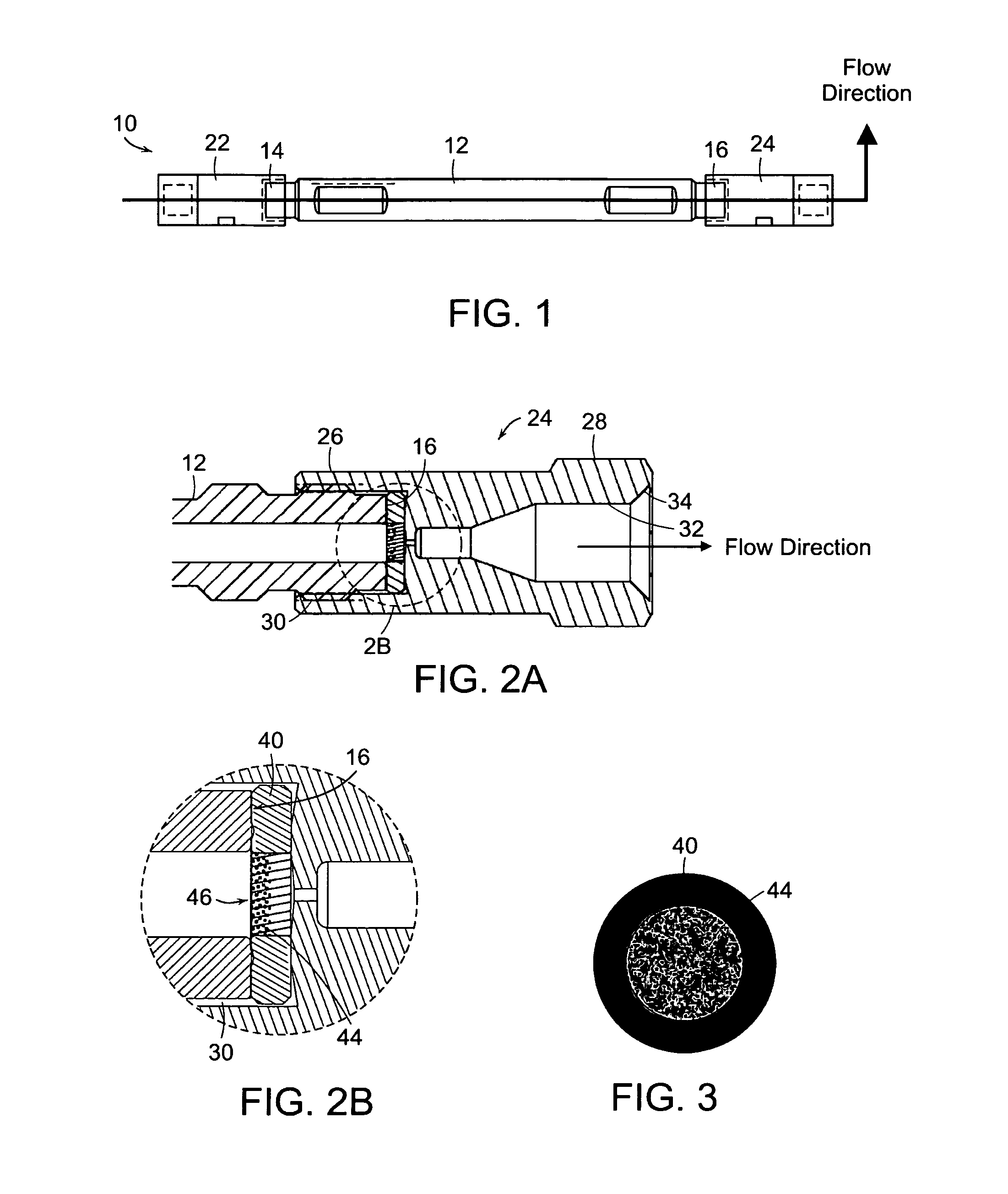
[0076]A porous support structure containing 3.5 micron secondary particles was filled as follows. A 0.5 media grade porous support structure was press fit into a circular planar ring (as shown in FIG. 3) that allows for a sealing surface. The sealing ring containing the porous support structure was placed into an outlet fitting. The outlet fitting was attached to an empty second end (outlet end) of a chamber (column). A 3 mL reservoir was attached to the first end (inlet) of the chamber. A tee was attached to the top of the reservoir. A pump was attached to the side opening of the tee. Then, 0.01 grams of 3.5 micron chromatographic packing materials was admixed and sonicated in 3 mL tetrahydrofuran (THF). The particle-solution was sonicated for 2 minutes. The particle-solution was poured or pipetted into the reservoir through the top opening of the tee. The particle-solution was topped off with approximately 2.2 mL of THF. The top opening in the tee, used to introduce the solutions,...

example 2

[0078]Frits containing 4 micron stainless steel particles were prepared as follows. A porous support structure (2.0 media grade sintered stainless steel) having a diameter of 2.1 mm and a thickness of 0.040 in. was press fit into a stainless steel sealing ring. The porous support structure was placed in a fixture whereby vacuum was drawn through the porous support structure. Narrowly sized particles (4 microns in diameter) were suspended in 10 mL toluene and mixed using a magnetic stir bar. A small volume of particle suspension was placed on the porous support structure and allowed to penetrate and pack into the void spaces within the support structure. The filled frit was wiped clean of excess particles and then sintered to 1900° F. for approximately one hour in a controlled H2 atmosphere to permanently immobilize the particles into a unified structure. Both 0.5 and 2.0 media grade frits were filled according to this process.

[0079]In Example 2, the described embodiment includes a “...

example 3

[0080]In the above examples, each of the frits preferably has a density of at least 50%. In other words, the void spaces or pores make up less than 50% by volume of the frits. The density of the frits increases after secondary particles are filled in the void spaces, thereby decreasing porosity.

[0081]In Example 3, depth of penetration was measured using 0.5 and 2.0 media grade porous support structures. For the 2.0 media grade porous support structure, the porosity of the unfilled structure was 32% (68% dense). For the 0.5 media grade porous support structure, the porosity of the unfilled structure was 19% (81% dense). Each support structure had a diameter of 2 inches and a thickness of 0.125 inches. Porosity was measured by comparing the weight of the porous support structure to the expected weight of a solid part of 316L stainless steel. Then, the porous support structures were slurry filled from one side with 4 micron stainless steel spherical particles (secondary particles) and ...


PUM

PropertyMeasurementUnit
sizeaaaaaaaaaa
diametersaaaaaaaaaa
sizeaaaaaaaaaa

Abstract

A frit (44) includes a porous support structure having a plurality of void spaces, where a plurality of secondary particles (46) are filled in the void spaces, the secondary particles (46) being dimensioned with respect to the void spaces such that the frit (44) retains packing materials with diameters of less than about 2.5 microns. Preferably one or more frits (44) are received in a high pressure liquid chromatography (HPLC) chromatographic column, where the column includes fittings and filter assemblies for receiving frits (44) at its inlet and outlet. The frit (44) can be constructed from a porous support structure with void spaces or pores that are filled with secondary particles (46) smaller those used to manufacture the support. The particles (46) contained in the void spaces are large enough to be retained by the support, but small enough to create a finer network of interconnected channels within the support's void spaces that are capable of retaining sub-2.5 micrometer particles.

Description

[0001]This application is a U.S. national phase application, pursuant to 35 U.S.C. §371, of PCT international application Ser. No. PCT / US2005 / 07152, filed Mar. 4, 2005, designating the United States and published in English on Sep. 22, 2005 as publication WO 2005 / 087340 A1, which claims priority to U.S. provisional application Ser. No. 60 / 550,993, filed Mar. 5, 2004. The entire contents of the aforementioned patent applications are incorporated herein by this reference.RELATED APPLICATION[0002]This application claims priority to: U.S. provisional application Ser. No. 60 / 550,993, filed 05 Mar. 2004. The aforementioned application is incorporated herein in its entirety by this reference.BACKGROUND OF INVENTION[0003]The subject invention relates to frits configured for use in high pressure liquid chromatography (HPLC) chromatographic columns, and more particularly, to a frit capable of retaining sub-2.5 micrometer particles. The frits also can serve as in-line filters arranged upstream...

Claims


Application Information

Patent Timeline
Patent Type & Authority Patents(United States)
IPC IPC(8): G01N30/60B01D15/08
CPCG01N30/603B01D15/08
Inventor IRANETA, PAMELA C.BELANGER, JONFISK, RAYMOND P.
Owner WATERS TECH CORP
Why Eureka
Try Eureka