
Combining a remote TLB lookup and a subsequent cache miss into a single coherence operation

a multi-processor computer system and cache miss technology, applied in the field of shared memory multi-processor computer systems, can solve the problems of large delay, increased tlb miss rate, significant impact on the performance of shared memory server systems, etc., and achieve the effect of facilitating the reduction of the critical path delay of a memory operation

Active Publication Date: 2015-04-07
RGT UNIV OF CALIFORNIA +1
View PDF4 Cites 4 Cited by
  • Summary
  • Abstract
  • Description
  • Claims
  • Application Information

AI Technical Summary

Benefits of technology

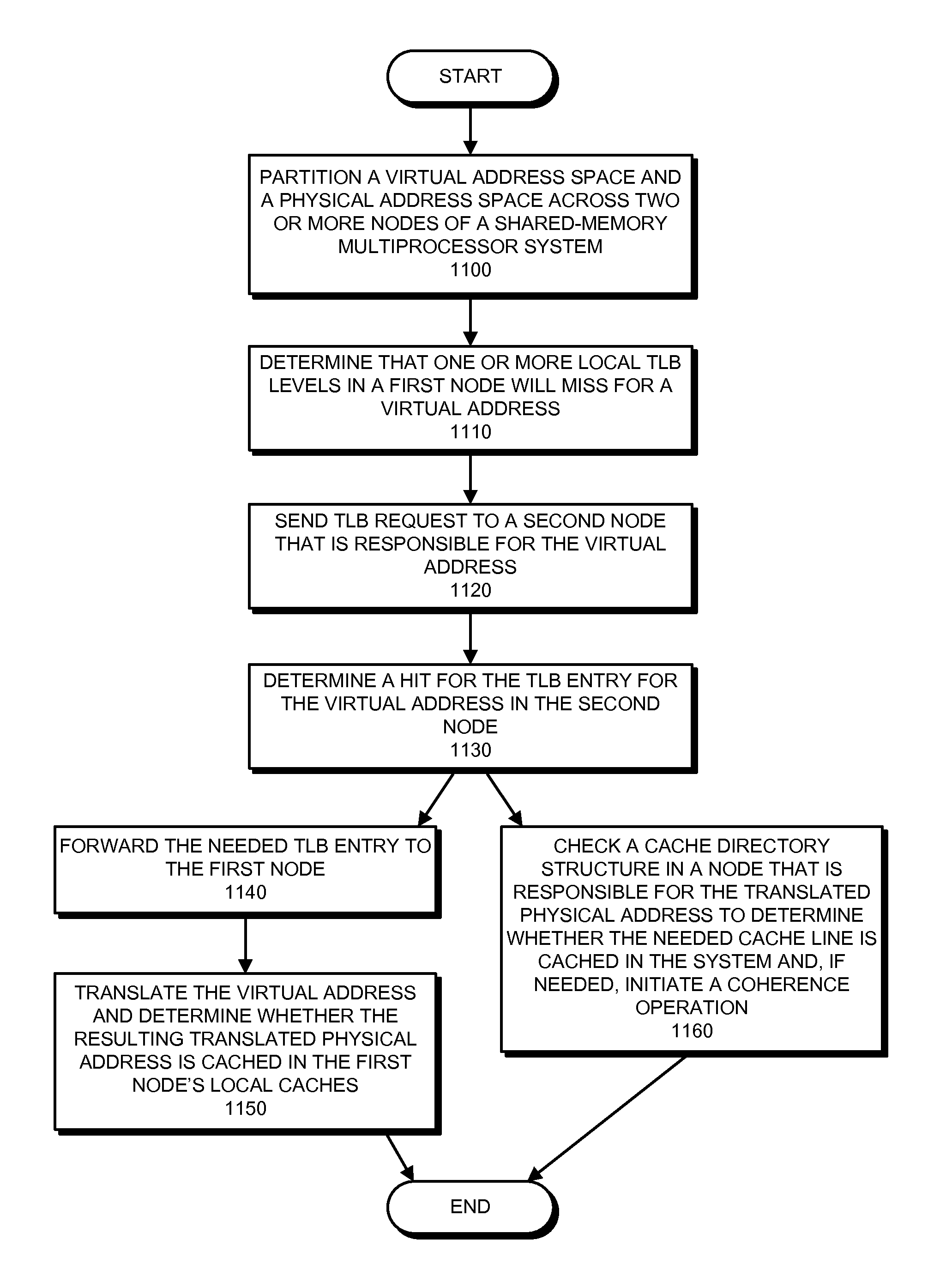
[0014]In some embodiments, the system strives to ensure that the physical address space is partitioned across the nodes of the shared-memory multiprocessor system such that a node that is responsible for a virtual page is also responsible for a physical page that the virtual page will map to. When possible, such “locality mapping” (which makes the same node both the “VA-home” for the virtual address as well as the “PA-home” for the corresponding physical address) reduces the number of request messages that need to be sent between the nodes of the shared-memory multiprocessor system.
[0015]In some embodiments, combining the TLB miss and the subsequent cache miss facilitates reducing the critical path delay of a memory operation by enabling a node with a TLB miss to complete two independent coherence operations in parallel.

Problems solved by technology

The latency caused by such address translation can significantly impact the performance of shared-memory server systems.
However, growing workload data-set sizes and an increase in the number of hardware threads that share a TLB increase TLB pressure, thereby resulting in increased TLB miss rates.
In the worst case, a memory instruction first misses in the TLB (e.g., during translation) and then also misses in the cache hierarchy, resulting in an even larger delay.

Method used


Image

  • Combining a remote TLB lookup and a subsequent cache miss into a single coherence operation
  • Combining a remote TLB lookup and a subsequent cache miss into a single coherence operation
  • Combining a remote TLB lookup and a subsequent cache miss into a single coherence operation

Examples


Embodiment Construction

[0036]The following description is presented to enable any person skilled in the art to make and use the invention, and is provided in the context of a particular application and its requirements. Various modifications to the disclosed embodiments will be readily apparent to those skilled in the art, and the general principles defined herein may be applied to other embodiments and applications without departing from the spirit and scope of the present invention. Thus, the present invention is not limited to the embodiments shown, but is to be accorded the widest scope consistent with the principles and features disclosed herein.

[0037]The data structures and code described in this detailed description are typically stored on a non-transitory computer-readable storage medium, which may be any device or non-transitory medium that can store code and / or data for use by a computer system. The non-transitory computer-readable storage medium includes, but is not limited to, volatile memory,...


PUM


Abstract

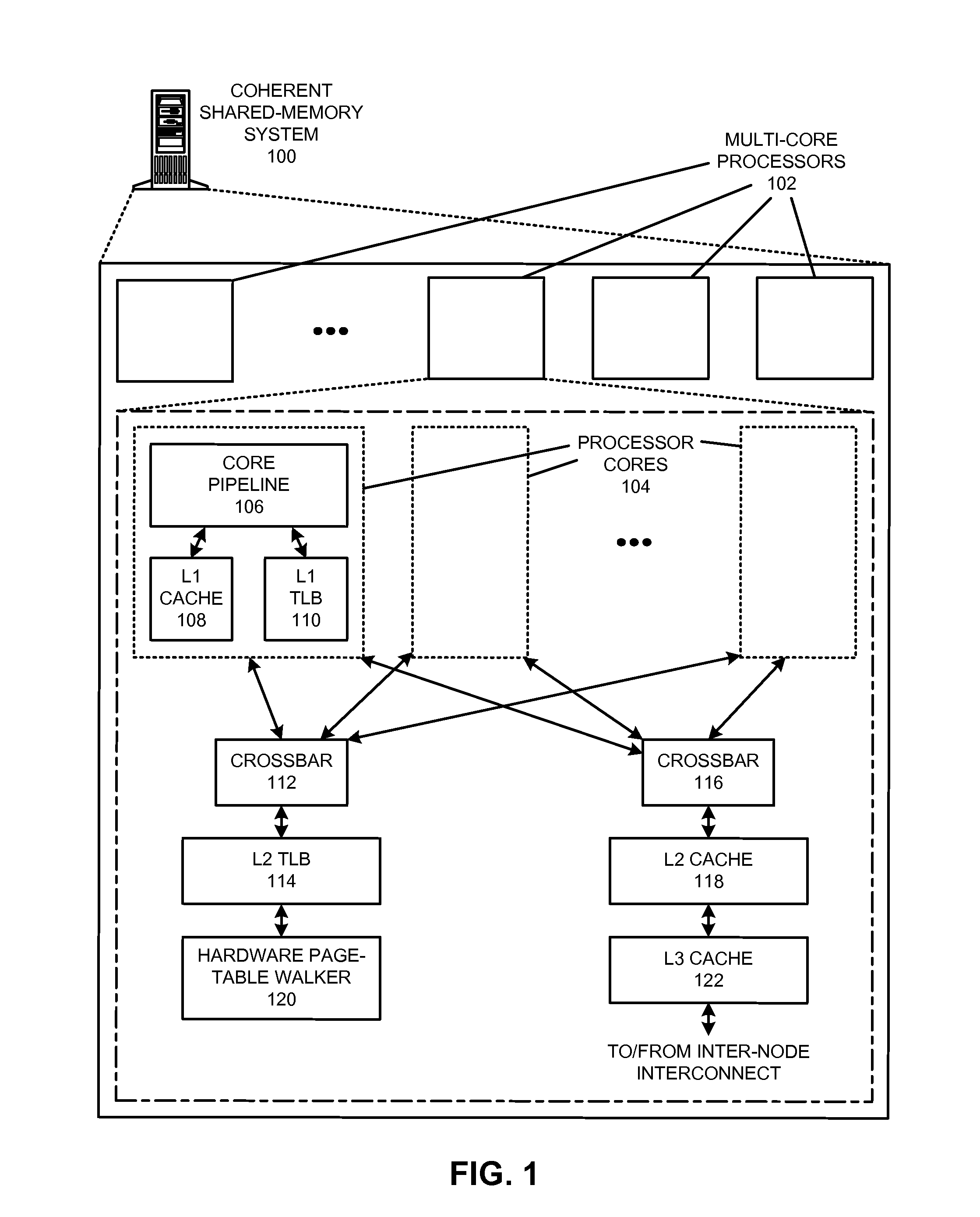
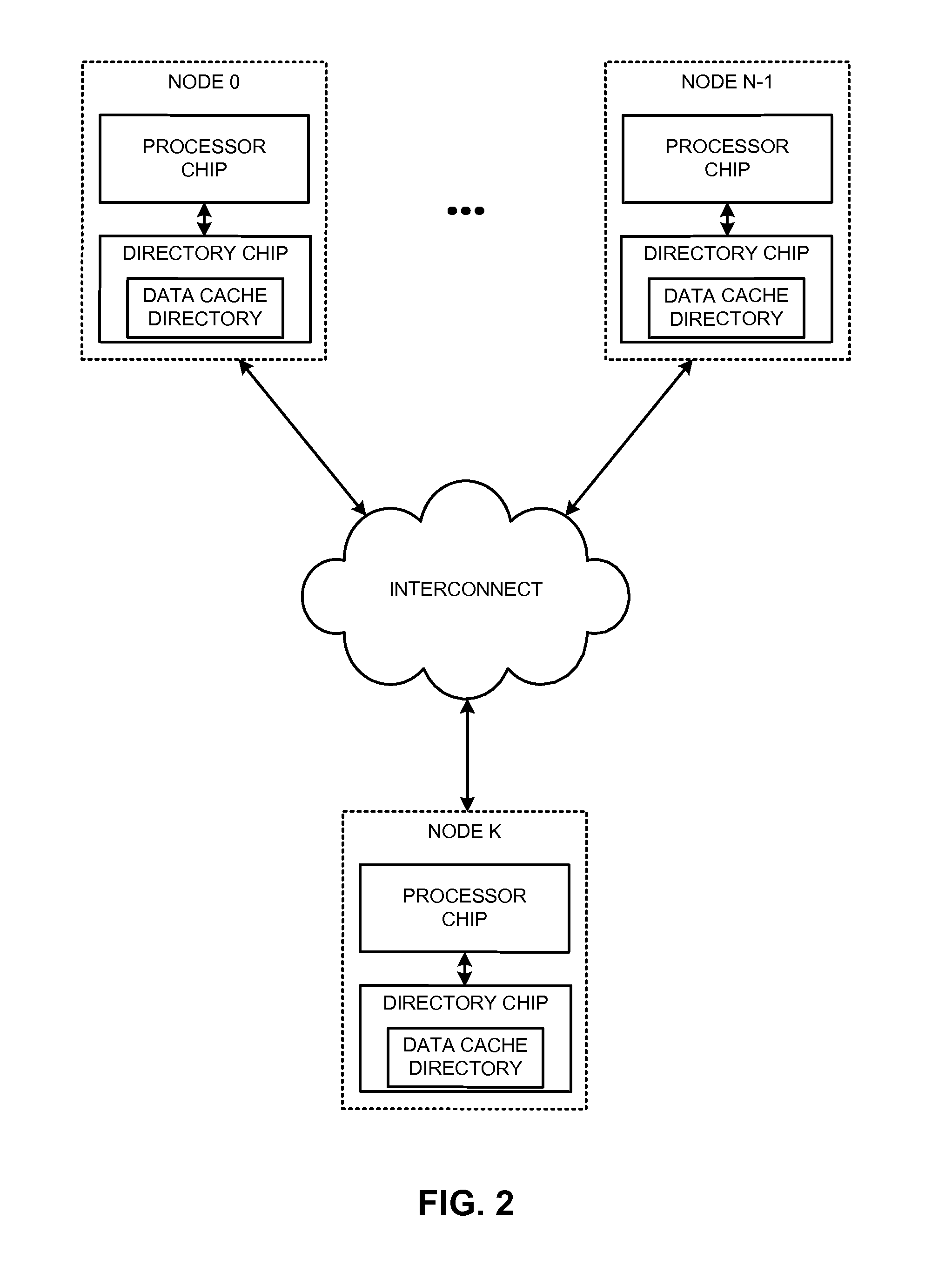
The disclosed embodiments provide techniques for reducing address-translation latency and the serialization latency of combined TLB and data cache misses in a coherent shared-memory system. For instance, the last-level TLB structures of two or more multiprocessor nodes can be configured to act together as either a distributed shared last-level TLB or a directory-based shared last-level TLB. Such TLB-sharing techniques increase the total amount of useful translations that are cached by the system, thereby reducing the number of page-table walks and improving performance. Furthermore, a coherent shared-memory system with a shared last-level TLB can be further configured to fuse TLB and cache misses such that some of the latency of data coherence operations is overlapped with address translation and data cache access latencies, thereby further improving the performance of memory operations.

Description

GOVERNMENT LICENSE RIGHTS[0001]This invention was made with United States Government support under Agreement No. HR0011-08-9-0001 awarded by the Defense Advanced Research Projects Administration (DARPA). The United States Government has certain rights in the invention.BACKGROUND[0002]1. Field of the Invention[0003]This disclosure generally relates to techniques for reducing latency in shared-memory multiprocessor computer systems. More specifically, this disclosure relates to techniques for reducing address-translation latency and parallelizing translation and coherency operations.[0004]2. Related Art[0005]Computer memory is typically divided into a set of fixed-length blocks called “pages.” An operating system can provide a virtual memory abstraction to give a program the impression that it is accessing a contiguous address space that is larger than the actual available physical memory of the underlying computer system. During operation, the operating system and hardware of the com...

Claims


Application Information

Patent Timeline
Patent Type & Authority Patents(United States)
IPC IPC(8): G06F12/10G06F12/08
CPCG06F12/1045G06F12/0817G06F2212/1024G06F2212/682
Inventor KOKA, PRANAYMCCRACKEN, MICHAEL O.SCHWETMAN, JR., HERBERT D.MUNDAY, DAVID A.ARDEVOL, JOSE RENAU
Owner RGT UNIV OF CALIFORNIA
Learn More