Fluid filter

a filter material and flue gas technology, applied in the field of flue gas filters, can solve problems such as reducing filtration area, and achieve the effect of improving filtration efficiency and suppressing deformation of filter materials

Inactive Publication Date: 2015-04-14
TOYOTA BOSHOKU KK
View PDF11 Cites 7 Cited by
  • Summary
  • Abstract
  • Description
  • Claims
  • Application Information

AI Technical Summary

Benefits of technology

[0009]The present invention has been made in light of the above current situation, and an object thereof is to provide a fluid filter which can ensure a filtration area while suppressing deformation of a filter material, thereby improving the filtration efficiency.
[0015]The fluid filter of the present invention is arranged in such a manner that a reinforcing member for reinforcing a folded filter material is provided. This arrangement can suppress deformation of the filter material when a fluid passes therethrough, and can also suppress close contact between the folds of the filter material to cause a decrease in filtration area. Further, this reinforcing member is provided in such a manner that, when the height of the folds is defined as h1, the lower end thereof is positioned above a position of 0.6 h1 from the upper end of the folds. Such an arrangement can decrease the contact area between the folds and the reinforcing member as compared with the case where the reinforcing member is provided over the entire height of the folds. As a result, it is possible to ensure the filtration area while suppressing deformation of the filter material and to improve the filtration efficiency.
[0016]Moreover, in the case where the reinforcing member is provided separately from the filter material and is formed in a comb-like shape to be inserted from above into the filter material, a fluid filter which can ensure the filtration area while suppressing deformation of the filter material with a simple structure can be realized.
[0017]In addition, in the case where the filter element is formed with a rib provided in a substantially center part of the ridge line direction of the folds of the filter material, the rib provided to extend in a direction crossing the ridge line direction of the folds, and the reinforcing member is provided in a substantially intermediate position between the rib and the edge part on the folded side of the filter material on both sides of the rib, the reinforcing member and rib support the filter material at predetermined intervals in the ridge line direction of the folds, thereby making it possible to suppress deformation of the filter material in the ridge line direction of the folds.
[0018]Moreover, in the case where the fluid filter is used, during filtration, in the state where the inner pressure of a filtration chamber formed by the upper case member, the lower case member and the filter element is lower than external pressure, and the upper case member is formed with a convex part abutting on the upper end face of the rib when the upper case member is deformed by a change in pressure during filtration, excessive deformation of the upper case member can be suppressed. Thus, the volume of the filtration chamber can be ensured. As a result, it is possible to ensure a fluid flow channel inside the filtration chamber and to suppress an increase in pressure loss during passage of a fluid.

Problems solved by technology

However, the comb-like reinforcing member, rib or the like for suppressing deformation of the filter material involved the problem that it is provided in close contact with or in abutment with the filter material, thereby causing a decrease in filtration area.

Method used


Image

  • Fluid filter
  • Fluid filter
  • Fluid filter

Examples


examples

[0046]Hereinafter, the present invention will be explained in detail by way of an Example with reference to the drawings. In the present Example, an oil filter for use in an automatic transmission is exemplified as the “fluid filter” according to the present invention.

[0047](1) Arrangement of the Oil Filter

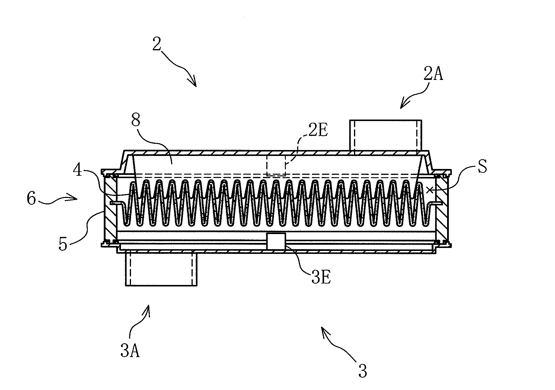
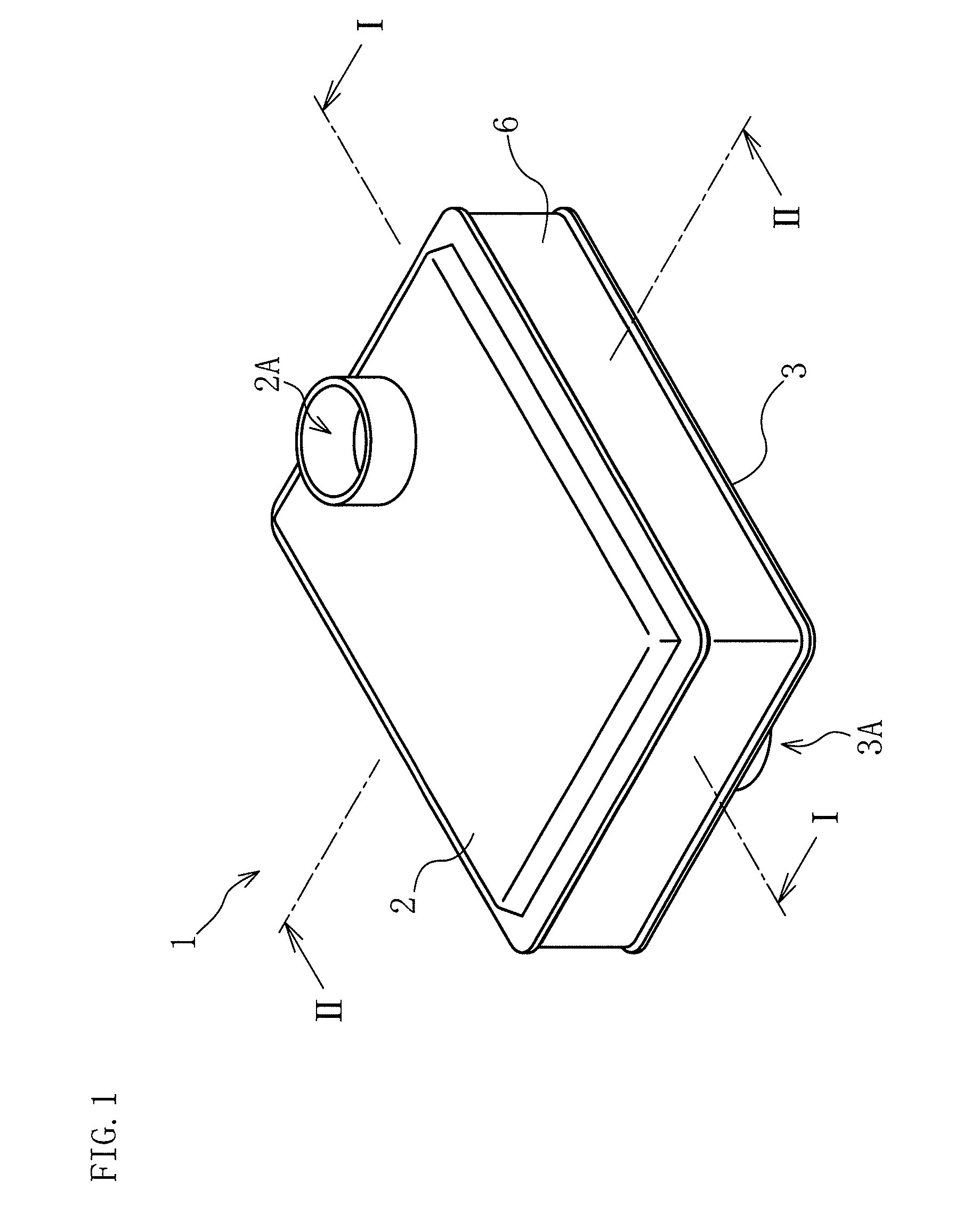
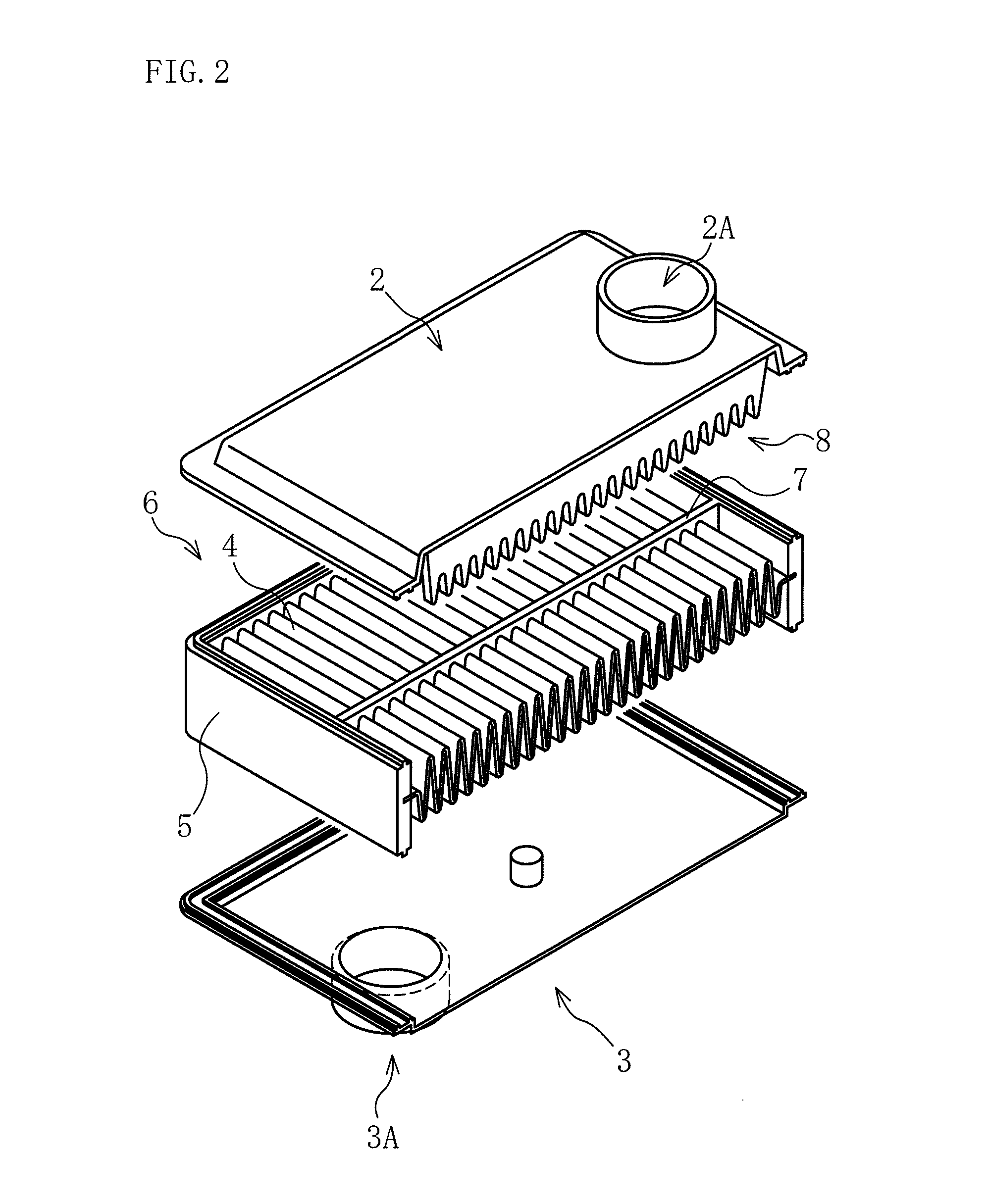
[0048]An oil filter 1 according to the present Example includes an upper case member 2 having a flow outlet 2A, a lower case member 3 having a flow inlet 3A, a filter element 6 having a filter material 4 and a holding frame 5 which holds the circumferential part of the filter material 4 and is sandwiched between the upper case member 2 and the lower case member 3, as shown in FIGS. 1 to 4. In this Example, the upper case member 2 and lower case member 3, respectively, are made of a laser permeable resin, and the holding frame 5 is made of a laser absorbable resin. These members are bonded by laser welding.

[0049]The filter element 6 according to the Example is formed integrally wit...


PUM

PropertyMeasurementUnit
heightaaaaaaaaaa
shapeaaaaaaaaaa
pressureaaaaaaaaaa

Abstract

A fluid filter including: an upper case member having a flow outlet; a lower case member having a flow inlet; a filter element having a folded filter material and a holding frame which holds the circumferential part of the filter material and is sandwiched between the upper case member and the lower case member; and a reinforcing member provided to extend in a direction crossing the ridge line direction of the folds of the filter material, the reinforcing member is provided in such a manner that, when the height of the folds is defined as h1, the lower end thereof is positioned above a position of 0.6 h1 from the upper end of the folds.

Description

CROSS-REFERENCE TO RELATED APPLICATIONS[0001]The present application claims priority under 35 U.S.C. §119 of Japanese Application No. 2011-148635 filed on Jul. 4, 2011, the disclosure of which is expressly incorporated by reference herein in its entirety.BACKGROUND OF THE INVENTION[0002]1. Field of the Invention[0003]The present invention relates to a fluid filter, more specifically, to a fluid filter which can ensure a filtration area while suppressing deformation of a filter material, thereby improving the filtration efficiency.[0004]2. Description of the Related Art[0005]Conventionally, as a fluid filter used for an automatic transmission of a vehicle and the like, for example, as shown in FIGS. 12A and 12B, a fluid filter including an upper case member 102 having a flow outlet 102a; a lower case member 103 having a flow inlet 103a; and a filter element 106 having a folded filter material 104 and a holding frame 105 which holds the circumferential part of the filter material 104 ...

Claims


Application Information

Patent Timeline
Patent Type & Authority Patents(United States)
IPC IPC(8): B01D29/07B01D46/00B01D46/10B01D46/52
CPCB01D29/07B01D46/0002B01D46/10B01D46/521B01D46/523B01D2201/127B29C65/1635B29C66/12443B29C66/24244B29C66/5432B29L2031/14
Inventor SAITO, YASUHIROSAKATA, HARUAKIMORI, TOSHIAKI
Owner TOYOTA BOSHOKU KK
Why Eureka
Try Eureka