
Device for detecting an object using SPAD photodiodes

a technology of photodiodes and objects, applied in the direction of distance measurement, counting objects on conveyors, instruments, etc., can solve the problems of reducing detection area and disturbing distance measurement, and achieve the effect of preventing distance measuremen

Active Publication Date: 2015-04-14
STMICROELECTRONICS (GRENOBLE 2) SAS
View PDF8 Cites 24 Cited by
  • Summary
  • Abstract
  • Description
  • Claims
  • Application Information

AI Technical Summary

Benefits of technology

The present invention is about a transparent plate that is put on a set of photodiodes that measure how long it takes for light to fly through something. The problem with this set-up is that the transparent plate can interfere with the distance measurements, which is what the invention is trying to fix. The technical effect is that the transparent plate prevents distortion in the measurements, resulting in more accurate and reliable data.

Problems solved by technology

The plate may reflect photons emitted by the source directly towards the photodiodes, which disturbs the distance measurement.
However, this arrangement can reduce a detection area which coincides with the largest possible area lighted by the source.

Method used


Image

  • Device for detecting an object using SPAD photodiodes
  • Device for detecting an object using SPAD photodiodes
  • Device for detecting an object using SPAD photodiodes

Examples


Embodiment Construction

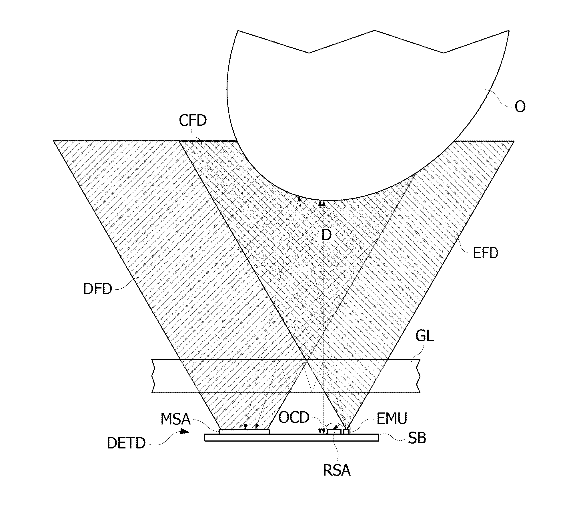
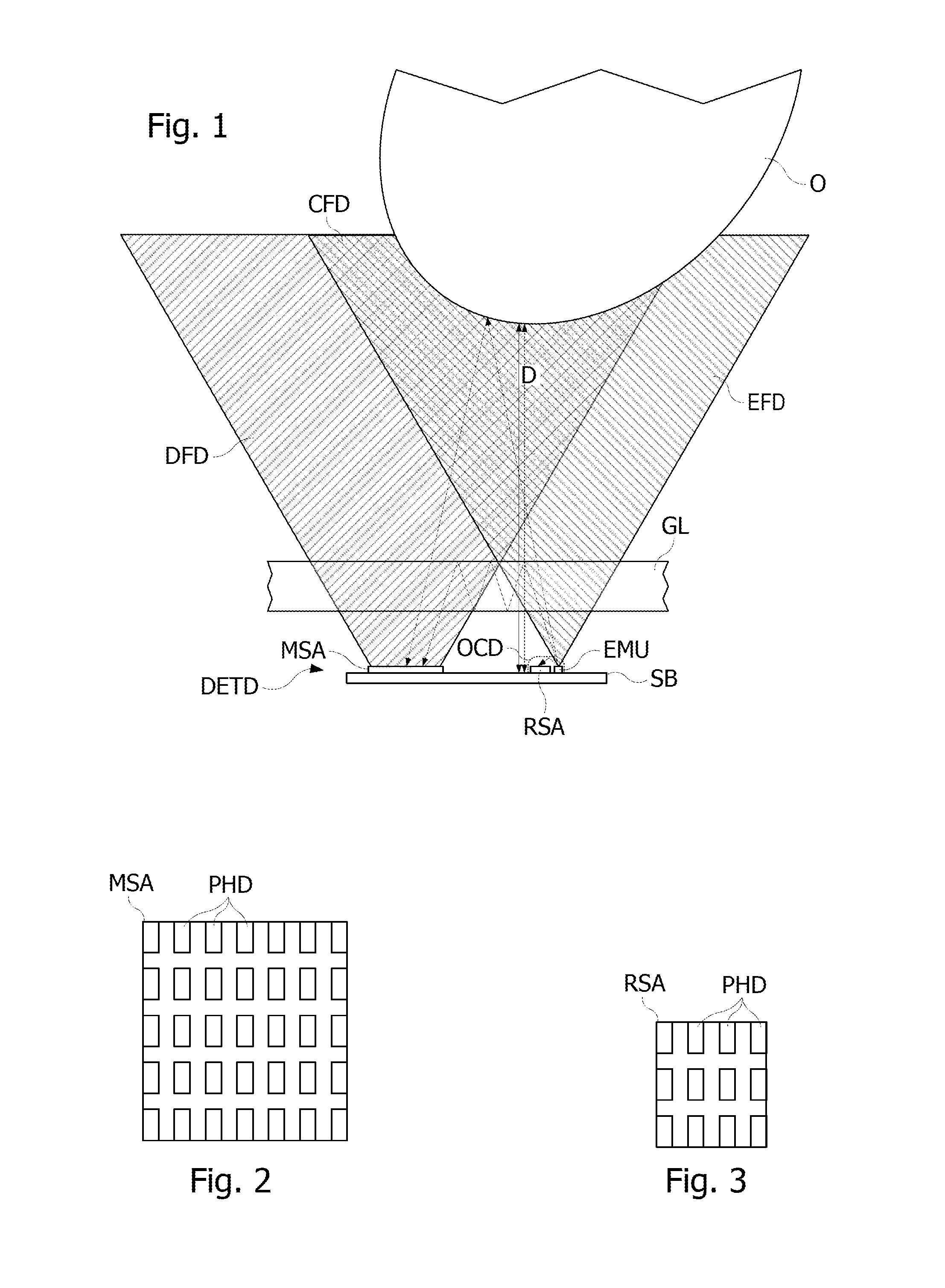
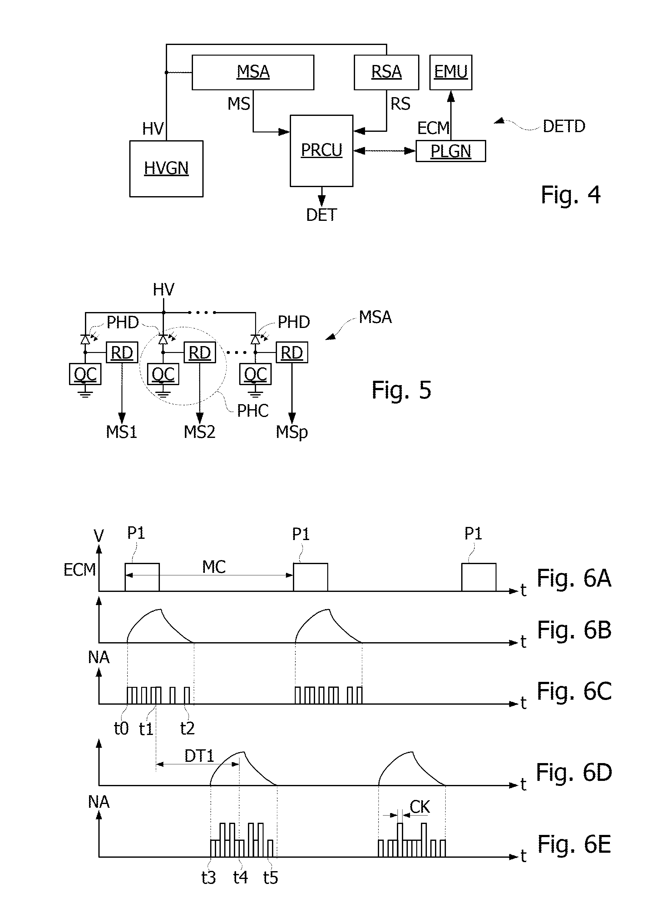
[0032]FIG. 1 shows a detection device DETD, according to one embodiment. Detection device DETD comprises a transmit unit EMU emitting photon pulses, a reception unit MSA, and a reference reception unit RSA, reception unit MSA and reference reception unit RSA being sensitive to the photon pulses emitted by transmit unit EMU. Transmit unit EMU, reception unit MSA, and reference reception unit RSA are formed on a wafer SB for example in a semiconductor material. Transmit unit EMU emits photon pulses in a transmit field EFD for example of conical shape whose top is centered on transmit unit EMU. Reception unit MSA is sensitive to photons coming from a detection field DFD which may also be of conical shape. Transmit field EFD and detection field DFD have a common area, forming a common detection field CFD in which an object O may be detected by detection device DETD by reflecting photons emitted by transmit unit EMU toward reception unit MSA.

[0033]Reference reception unit RSA is opticall...


PUM


Abstract

The disclosure relates to a method for detecting the presence of an object near a detection device, comprising: emitting pulses of an incident photon beam, detecting photodiodes which trigger avalanche after the reception by the photodiode of at least one photon of a reflected photon beam produced by a reflection of the incident beam on an object near the detection device, determining a distance between the photodiodes and an object in a detection area, as a function of the time between a transmit time of the incident beam and avalanche triggering times of the photodiodes, and correcting the distance determined as a function of a calibration measurement obtained in the absence of object in the detection area, to compensate for photon reflections on a transparent plate arranged between the photodiodes and the detection area.

Description

BACKGROUND[0001]1. Technical Field[0002]The present disclosure relates to a device for detecting and measuring the distance from an object, based on a propagation time of a photon beam emitted in the form of pulses and reflected on the object. The present disclosure applies in particular to touch screens such as those used in mobile phones, and to the detection of an object near such a screen.[0003]2. Description of the Related Art[0004]It is known to use photodiodes as a distance detection and measurement element, using an avalanche phenomenon which may occur in the PN junctions of photodiodes. An avalanche phenomenon may occur in a diode PN junction when the diode is reverse biased near the junction breakdown voltage. This phenomenon can be used in two ways in an avalanche photodiode. If the avalanche photodiode is reverse biased just below the breakdown voltage, the photodiode then generates an electric current proportional to the intensity of the photon flux received by the phot...

Claims


Application Information

Patent Timeline
Patent Type & Authority Patents(United States)
IPC IPC(8): G06M7/00G01C3/08G01S7/4861G01S7/497G01S17/10
CPCG01C3/08G01S17/10G01S7/4861G01S7/497
Inventor DRADER, MARC
Owner STMICROELECTRONICS (GRENOBLE 2) SAS
Learn More