X-ray CT apparatus and image processing apparatus

a computed tomography and x-ray technology, applied in tomography, material analysis using wave/particle radiation, instruments, etc., can solve the problems of not being able to obtain ideal counter data and not being able to introduce this techniqu

Active Publication Date: 2015-04-14
TOSHIBA MEDICAL SYST CORP
View PDF9 Cites 4 Cited by
  • Summary
  • Abstract
  • Description
  • Claims
  • Application Information

AI Technical Summary

Benefits of technology

[0007]It is an object to provide an X-ray CT apparatus and image processing apparatus which can reduce artifacts in a reconstructed image while maintaining the resolution of the reconstructed image by using a simple method.

Problems solved by technology

The above flying focal spot technique requires a dedicated X-ray tube, and hence it is not easy to introduce this technique.
In addition, according to the QQ offset technique, when using an apparatus having a cone angle such as an AD (Area Detecting) CT, since real data and counter data do not exist on the same plane around this cone angle, it is not possible to obtain ideal counter data.

Method used


Image

  • X-ray CT apparatus and image processing apparatus
  • X-ray CT apparatus and image processing apparatus
  • X-ray CT apparatus and image processing apparatus

Examples


first embodiment

[0014]The first embodiment will be described first.

[Overall Arrangement of X-Ray CT Apparatus]

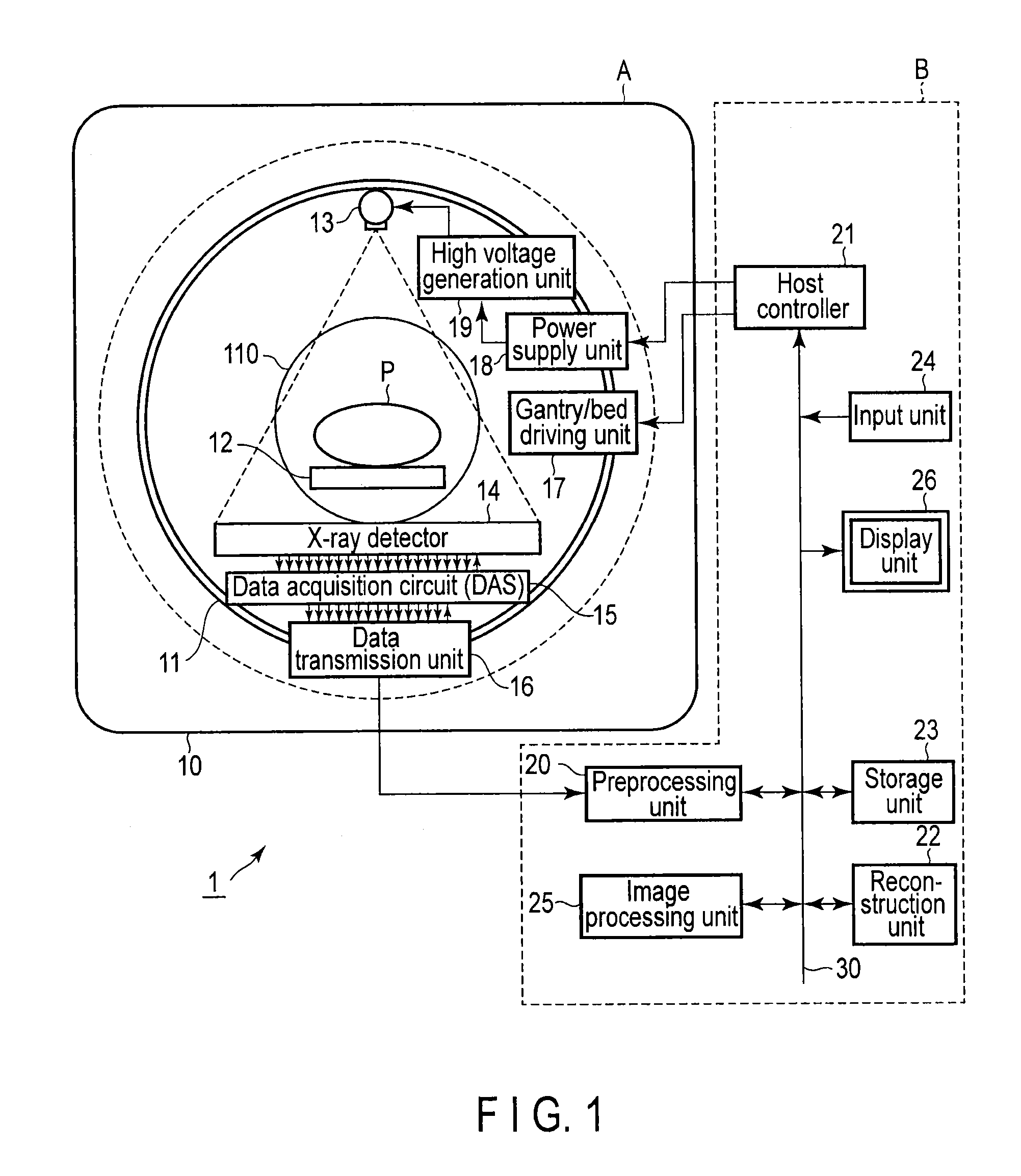
[0015]FIG. 1 is a block diagram showing the overall arrangement of an X-ray CT apparatus 1 according to this embodiment. As shown in FIG. 1, the X-ray CT apparatus 1 includes a gantry device A and a console device B.

[0016]The gantry device A irradiates an object with X-rays and acquires projection data (or raw data) by detecting the X-rays transmitted through the object. Note that X-ray CT systems include various types, e.g., a rotate / rotate type in which an X-ray tube and an X-ray detector system rotate together around an object, and a stationary / rotate type in which many detection elements are arrayed in the form of a ring, and only an X-ray tube rotates around an object. The embodiments can be applied to either type. In this case, a rotate / rotate type X-ray CT apparatus, which is currently the mainstream, will be exemplified.

[0017]As shown in FIG. 1, the gantry device A includes a fixed ...

second embodiment

[0053]The second embodiment will be described next.

[0054]This embodiment differs from the first embodiment in that it obtains output data Out[ch] by performing weighted addition of input data In[ch] and the data obtained by applying LPF processing to input data In[ch] instead of using convolution with a Gaussian filter.

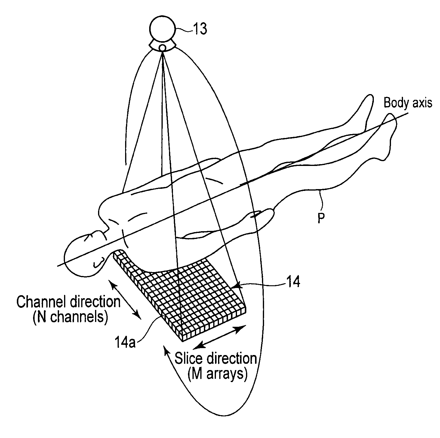
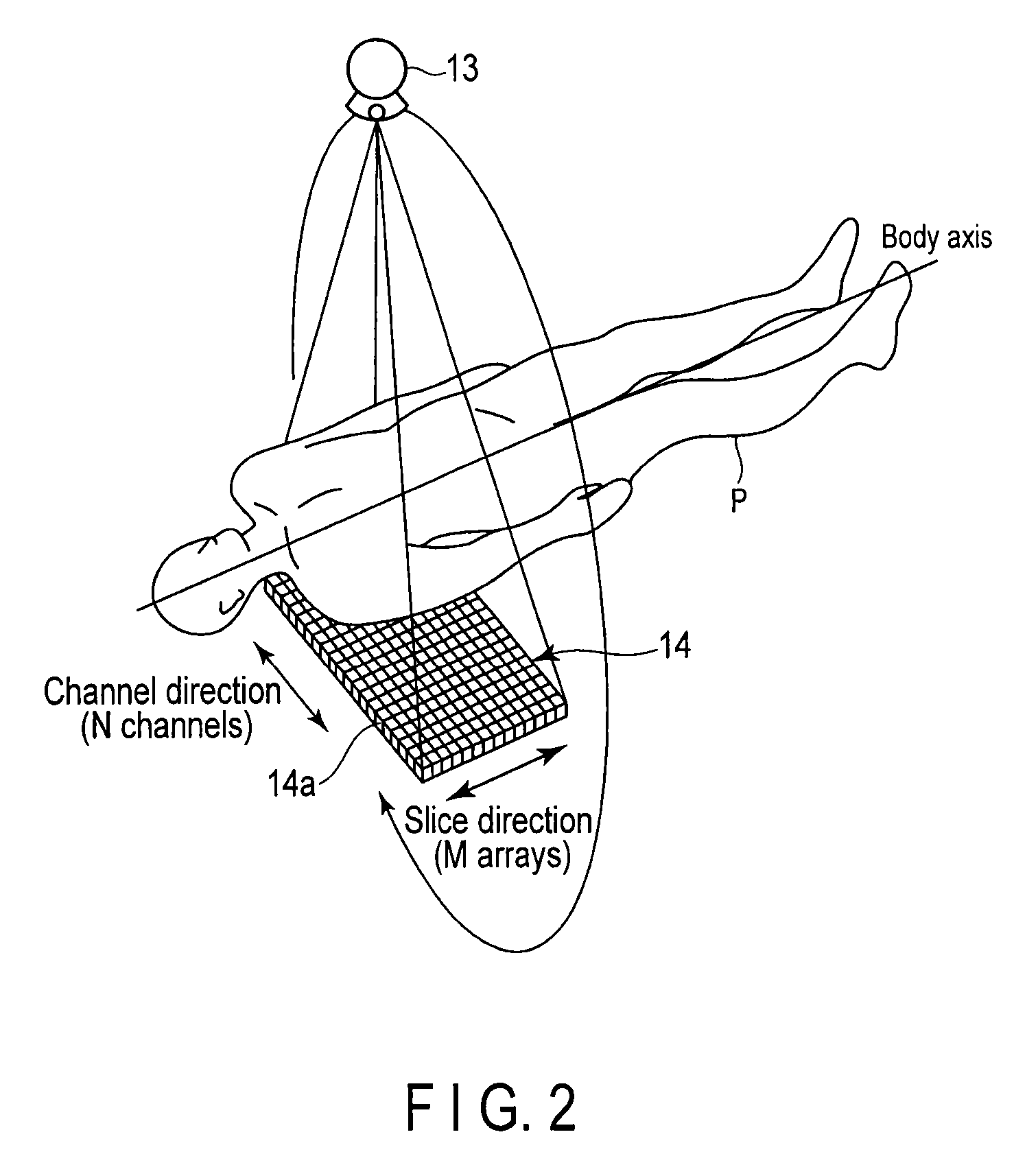
[0055]The arrangement shown in FIGS. 1 and 2 and the processing procedure shown in FIG. 3 are the same as those in the first embodiment. In step S4, an image processing unit 25 obtains output data Out[ch] by the following procedure.

[0056]That is, the image processing unit 25 uniformly applies LPF processing to input data In[ch]. The result obtained by applying this LPF processing to the data is represented by LPF data LPF_In[ch]. This processing uses a convolution of a three-point filter such that the data obtained by performing weighted addition of input data In[ch−1], In[ch], and In[ch+1] with ratios of 0.3, 0.4, and 0.3 is used as LPF data LPF_In[ch]. Note that LPF...


PUM

PropertyMeasurementUnit
smoothing strengthaaaaaaaaaa
weightaaaaaaaaaa
Computed Tomographyaaaaaaaaaa

Abstract

According to one embodiment, an X-ray CT apparatus includes an generation unit, detection unit, processing unit, and reconstruction unit. The generation unit irradiates an object with X-rays. The detection unit includes detection elements corresponding to a plurality of channels, which output detection signals upon detecting X-rays. The processing unit smoothes projection data constituted by numerical values corresponding to signals output from the elements so as to more strongly smooth a portion exhibiting a larger amount of change in the numerical value. The reconstruction unit reconstructs an image by using a plurality of projection data smoothed by the image processing unit.

Description

CROSS-REFERENCE TO RELATED APPLICATIONS[0001]This application is a Continuation Application of PCT Application No. PCT / JP2012 / 075830, filed Oct. 4, 2012 and based upon and claiming the benefit of priority from Japanese Patent Application No. 2011-225260, filed Oct. 12, 2011, the entire contents of all of which are incorporated herein by reference.FIELD[0002]Embodiments described herein relate generally to an X-ray CT (Computed Tomography) apparatus which captures a tomographic image by irradiating an object with X-rays and an image processing apparatus which processes the image captured by the X-ray CT apparatus.BACKGROUND[0003]An X-ray CT apparatus is designed to rotate an X-ray source and an X-ray detector around the body axis of an object, cause the X-ray source to irradiate the object with X-rays, and reconstruct a tomographic image based on the projection data obtained by detecting the X-rays transmitted through the object using the X-ray detector. This apparatus plays an impor...

Claims


Application Information

Patent Timeline
Patent Type & Authority Patents(United States)
IPC IPC(8): G01N23/083G06K9/60G06K9/44A61B6/00A61B6/03G01N23/04G06T11/00
CPCG06T11/003G01N23/046A61B6/032A61B6/5205Y10S378/901A61B6/5258
Inventor NAKANISHI, SATORU
Owner TOSHIBA MEDICAL SYST CORP
Why Eureka
Try Eureka