Method and system for applying a road surface

a road surface and road technology, applied in the field of road surface application, can solve the problems of laying equipment coming to a standstill, complicated and time-consuming, and material cooling on the truck, so as to reduce the mass flow of laying equipment, reduce the cooling effect, and reduce the cooling

Active Publication Date: 2015-04-21
JOSEPH VOEGELE AG
View PDF47 Cites 27 Cited by
  • Summary
  • Abstract
  • Description
  • Claims
  • Application Information

AI Technical Summary

Benefits of technology

[0008]It is the object of the present invention to improve a method and a system for applying a road surface to the effect that road surface of an even better quality can be prepared.
[0012]The advantage of the method according to the invention is that influences, such as the weather, defects, traffic jams, breaks or work-related changes in the speed of the road finishing machine, are directly detected and can now be consulted for controlling the mixing plant and / or the supply chain. If, for example, delays in the laying process result from traffic jams or defects, the rate of production of the laying material in the mixing plant can be slowed down, or the mass flow delivered to the road finishing machine can be reduced. This avoids producing too much laying material or transporting laying material to the site that cannot be laid or accumulates on site and cools down too much. Inversely, this prevents having the laying equipment come to a standstill. A clear improvement in quality is achieved with a laying process that is as uniform as possible. Supply gaps where no truck is on the site are equally grave for the quality of the asphalt as the asphalt cools down t on the truck. As a result, the previously applied asphalt cools down directly behind the finishing machine without it being possible to recompact it. When the machine is started again, there is a risk in that uneven surfaces are generated transversely to the direction of traffic. Quality losses or returns and the complicated disposal of excessively produced laying material can be avoided. Moreover, the provision of an asphalt reserve that is ultimately not used for the laying process can be eliminated. This results in saving resources, costs and energy. Employment of this system and method makes sense both ecologically and economically. If one detects at the road finishing machine that an efficient laying of the supplied laying material can be effected, the temperature of the laying material produced in the mixing plant can be reduced, as this material cools down less due to the efficient laying process. With this approach, energy can be saved.DETAILED DESCRIPTION OF THE INVENTION
[0016]If several mixing plants are provided, preferably a change of the amount of laying material requested by the road finishing machine is distributed proportionally to the maximum capacity of the individual mixing plants or proportionally to the daily amount of laying material ordered from the individual mixing plants according to a key. Using this system promotes uniform operation of the construction process.
[0018]Here, it is particularly advantageous if the mass flow of laying material currently present in the supply chain is displayed at the road finishing machine. An operator of the road finishing machine can then adapt the laying speed of the road finishing machine to this mass flow to be received. In this manner, the laying speed can be slowed down to avoid a standstill of the road finishing machine and quality losses caused thereby, for example in case of an imminent undersupply with laying material.

Problems solved by technology

This, however, does not prevent several trucks from accumulating in front of the road finishing machine, for example in delays in the laying process, so that the laying material on the truck cools down to an undesired degree.
If the laying material cools down too much, it can even become useless, so that it has to be disposed of in a complicated and time-consuming manner.

Method used


Image

  • Method and system for applying a road surface
  • Method and system for applying a road surface
  • Method and system for applying a road surface

Examples


Embodiment Construction

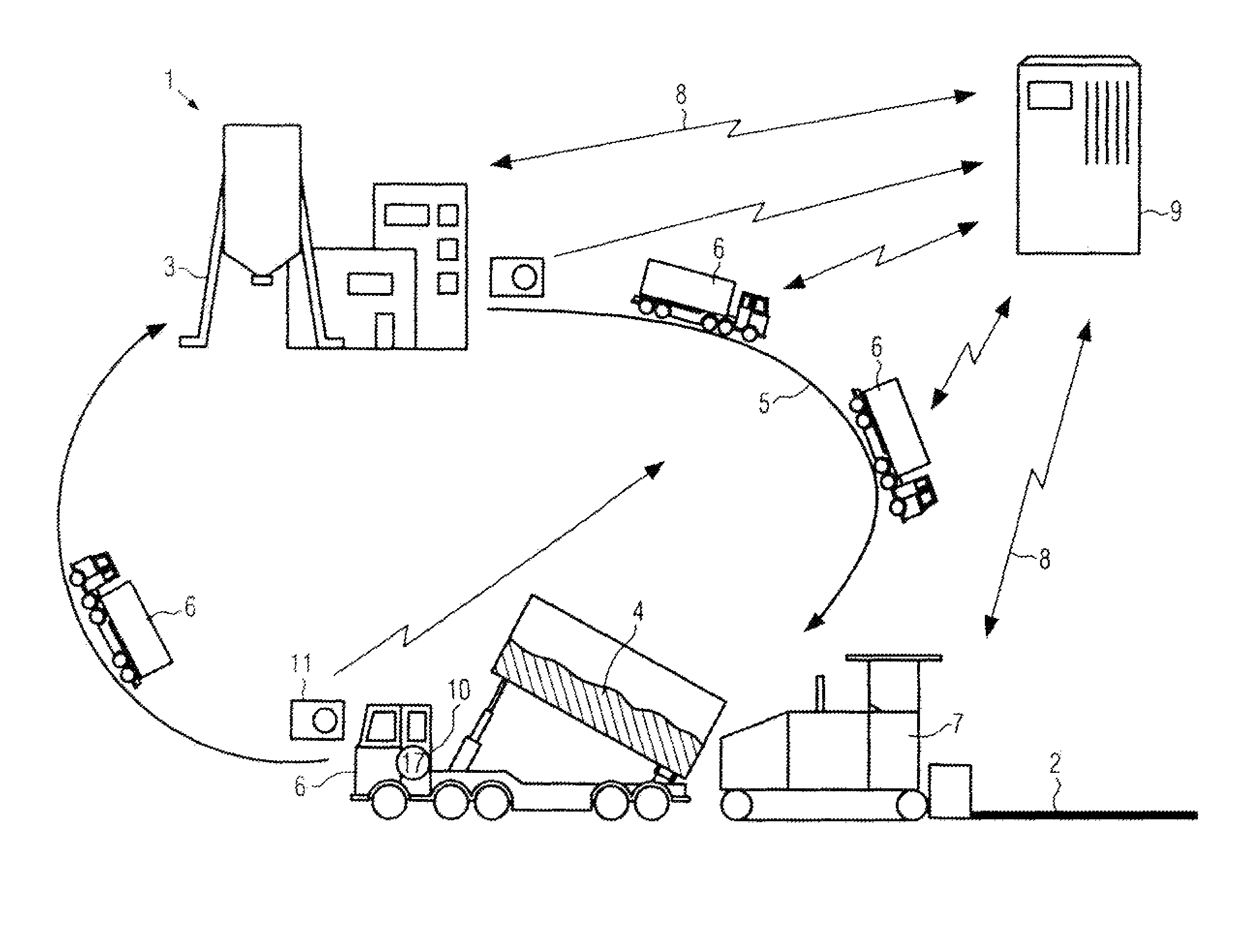
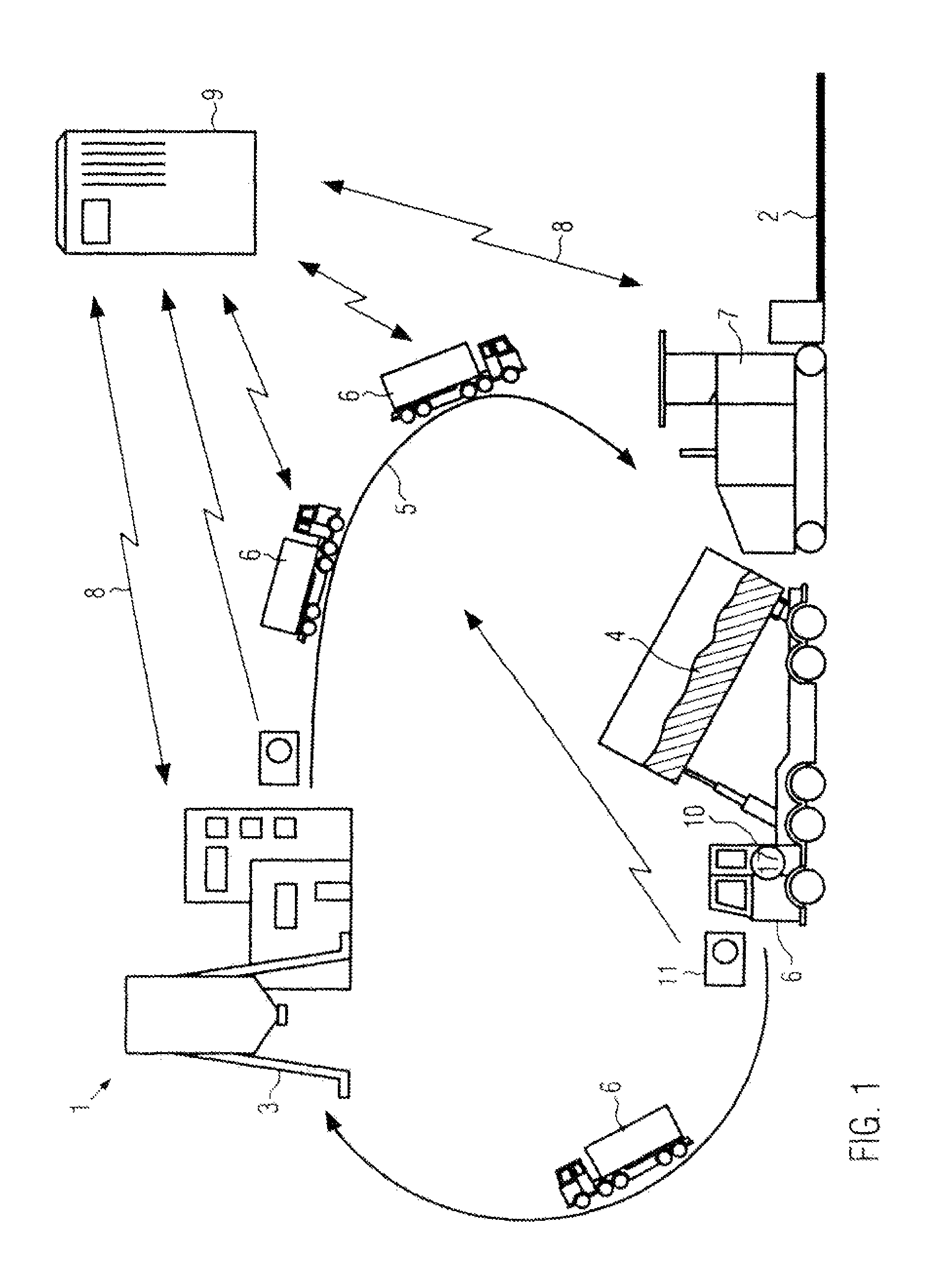
[0013]In the method according to the invention, one single mixing plant can be employed, or as an alternative, a plurality of mixing plants can be used and the laying material produced by these plants can be supplied to one or to several sites. In the sense of the invention, a supply chain comprises at least one, preferably several transport vehicles which transport the laying material from the mixing plant or the mixing plants to the road finishing machine. A further embodiment can include a transport chain to several road finishing machines, wherein the road finishing machines lay various mixed asphalt materials which must be supplied in the proper sequence (just in sequence).

[0014]Preferably, a demand forecast is established at the road finishing machine, and the request commands are established depending on this demand forecast. The demand forecast can be either established manually or by means of a suited computer program. It assesses which amount of laying material can be proc...


PUM


Abstract

A method and a system for applying a road surface using a mixing plant for producing laying material, a road finishing machine processing the laying material to a road surface, and a supply chain transporting the laying material from the mixing plant to the road finishing machine. Request commands are transmitted from the road finishing machine to the mixing plant and / or to the supply chain, and, depending on these request commands, the production rate of the laying material in the mixing plant, the temperature of the laying material produced in the mixing plant, and / or the mass flow of laying material supplied to the road finishing machine per time unit by means of the supply chain are adjusted.

Description

BACKGROUND OF THE INVENTION[0001]The present invention relates to a method for applying a road surface using at least one mixing plant for producing laying material, a road finishing machine for applying the laying material to a road surface, and a supply chain for transporting the laying material from the mixing plant to the road finishing machine.[0002]Preparing a road surface is an extremely complex working process. Usually, not only many different working machines, such as, for example, a mixing plant, trucks, feeders, road finishing machines and rollers, are involved in this working process, but also many different persons, sometimes with different degrees of experience. Moreover, the preparation of a road surface is influenced by many factors, for example by the temperature and composition of the laying material, the duration of the transport of the laying material to the construction site, the laying speed, the adjustment of the compacting units at the road finishing machine,...

Claims


Application Information

Patent Timeline
Patent Type & Authority Patents(United States)
IPC IPC(8): E01C23/07E01C3/06E01C19/12E01C19/00E01C19/48
CPCE01C19/00E01C19/48E01C2301/02
Inventor BUSCHMANN, MARTINWEISER, RALFRUTZ, ARNOLDEUL, ACHIM
Owner JOSEPH VOEGELE AG
Why Eureka
Try Eureka