Transition assemblies for building opening

a technology for transition assemblies and building openings, applied in the field of building construction, can solve the problems of limited thermoplastic welding options for effective sealing of this material, and achieve the effect of avoiding environmental penetration

Inactive Publication Date: 2015-05-05
MICHAUD DONALD A
View PDF1 Cites 6 Cited by
  • Summary
  • Abstract
  • Description
  • Claims
  • Application Information

AI Technical Summary

Benefits of technology

[0008]The present invention relates to a sealing assembly, for sizing and adapting a window frame or a door frame into a building opening with proper insulation and gap sealing arrangements therearound, so as to enable that window frame or door frame to fit snugly within that opening and eliminate environmental penetration either from the outside-in or from the inside-out.
[0011]The engaging ridge has an elongated truncated receiving channel extending longitudinally therealong. The truncated receiving channel preferably has extruded barb-like teeth extending therewithin. The sealing assembly further includes an elongated flexible air fin. The air fin preferably has an inner layer of soft insulated material extending through its entire length. The air fin has longitudinal edges which preferably have a saw tooth configuration of thereon, so as to be easily insertable and receivable snugly by the receiving channel on the receiving ridge of the elongated foam body member. The elongated foam body member is held within the peripheral receiving frame which surrounds the door or window.

Problems solved by technology

The “air fin” however is co-extruded onto the “foam body” and is comprised of polyethylene, and the options for effectively sealing this material are unfortunately limited to thermoplastic welding.

Method used


Image

  • Transition assemblies for building opening
  • Transition assemblies for building opening
  • Transition assemblies for building opening

Examples


first embodiment

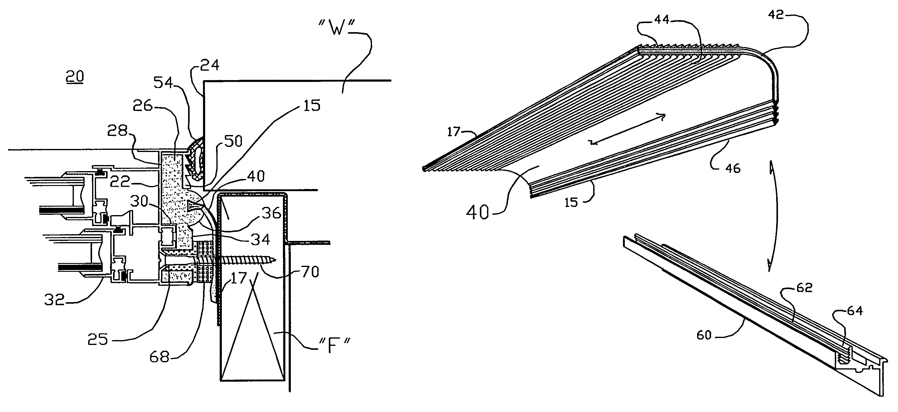
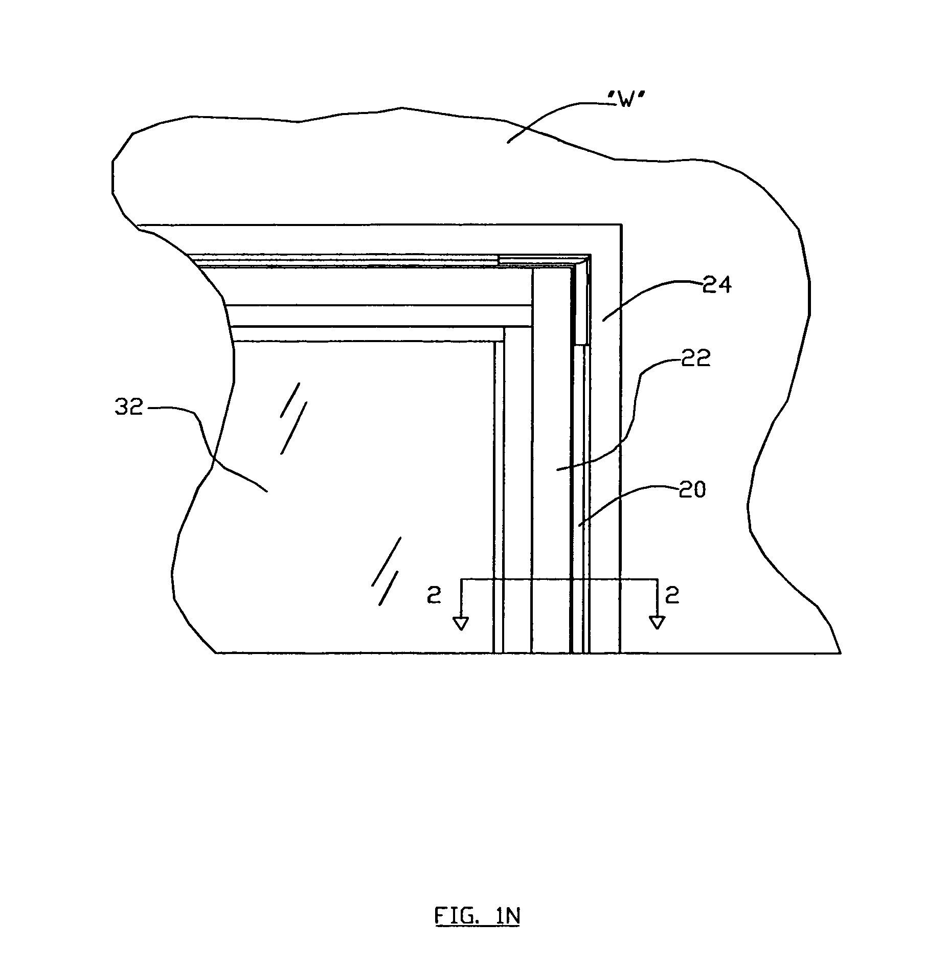
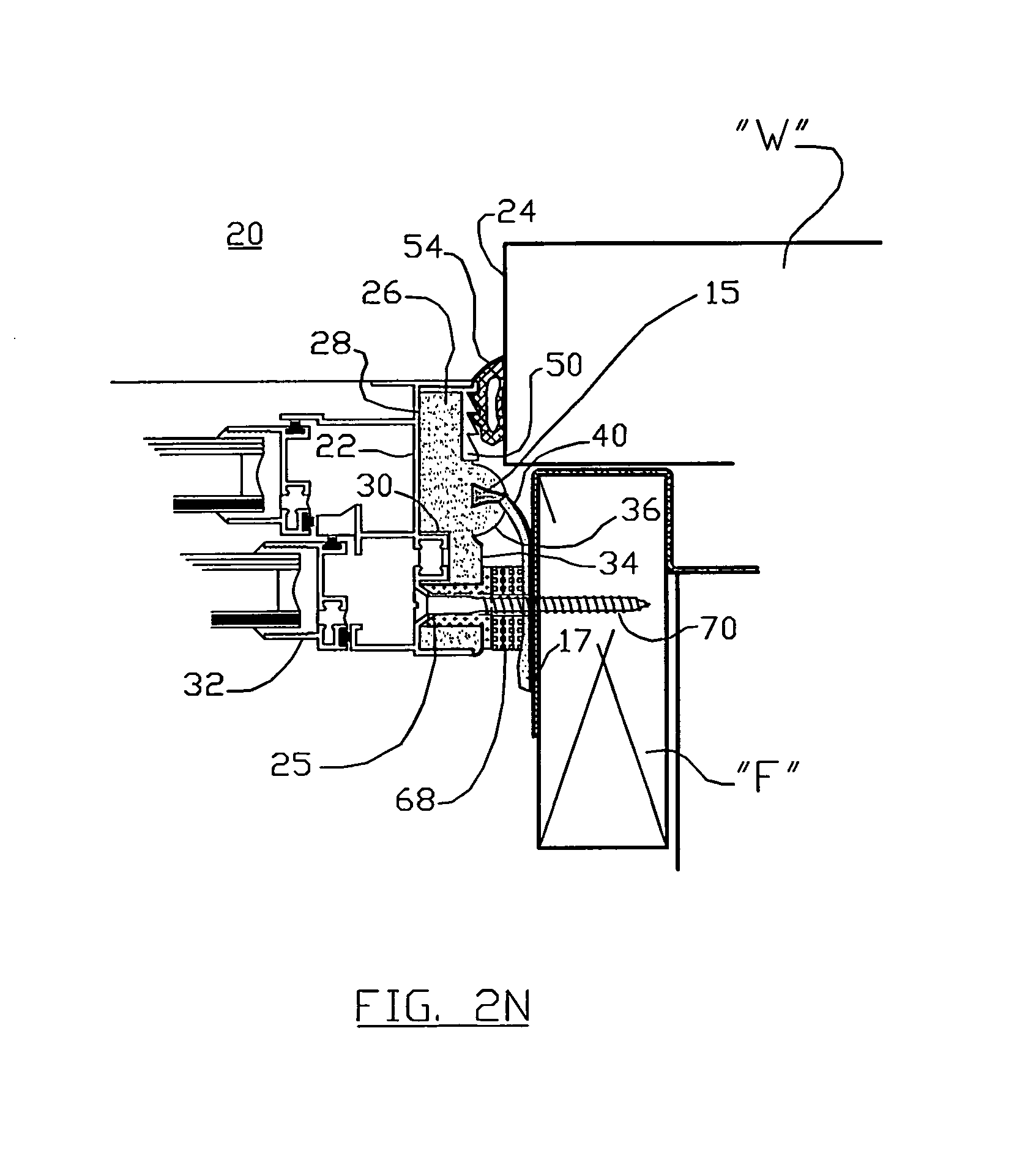
[0031]The sealing assembly 20 comprises an extruded, elongated, generally rectilinearly shaped foam body insulating member 26, shown in assembled position in FIG. 2N and in perspective in FIG. 3N. The foam body insulating member 26 is preferably comprised of a closed cell foam of varying densities, and is shaped to provide desired surface contours for mating with supplemental components. The foam body insulating member 26 has a first or inwardly directed enclosure-frame facing side 28 which faces and mates snugly with a channel 30 of a wall-opening facing side of the window / door frame 22, the frame 22 being that which peripherally surrounds and supports a window sash or door 32 therewithin, as represented in FIGS. 1N and 2N. The foam body insulating member 26 also has a wall opening facing side 34 with extrusion-effected seal-engaging shapes as may be seen in FIG. 3N, as well as an elongated, angled “caulking band” attachment strip 27 for secure placement of a “caulking band” theret...

second embodiment

[0036]the “caulk band” is shown as an engagement flange 60, in FIGS. 5N, 6N and 7N. This engagement flange caulk band 60 has a receiving channel 62 therein, machined, formed or co-extruded therewith, having internal ridges 64 extending therealong, as may be best seen in FIGS. 5N, 6N and 7N. Those internal ridges 64 are utilized to fully grasp one longitudinal side of the elongated air fin 40 with the arrowhead ridges 46 thereon, when the air fin 40 is inserted therewithin, as represented 5N, 6N and 7N. An injectable sealant material 41 is preferably disposed around the periphery of the engagement flange 60, as represented in FIG. 5N, to provide a first outside barrier 40 to the multiple inside environmental barriers, that is, the air fin 40 and the elongated fender 68.

[0037]The sealing assembly 20 in one preferred embodiment is established when the receiving frame 22, which holds the window or door 32 therewithin, is secured to the frame “F” of the opening 24 in the building wall “W...


PUM

PropertyMeasurementUnit
flexibleaaaaaaaaaa
perimeteraaaaaaaaaa
densitiesaaaaaaaaaa

Abstract

A sealing assembly for securely and insulatively maintaining a window or door and surrounding frame arrangement within an opening of a building wall. The sealing assembly comprises an elongated foam cell body member arranged within a channel of the surrounding frame arrangement of the window or door, wherein the elongated cell body member has a wall-opening-facing side. An elongated caulking band flange member is arranged in abutting relationship with a corner of the elongated foam cell body member. A thin flexible air fin is arranged in close environmental sealing relationship with the elongated foam cell body member and the opening in the wall of the building. A securement member is arranged to fasten the window or door surrounding frame arrangement, the elongated foam cell body member and the air fin, all to the building wall opening.

Description

BACKGROUND OF THE INVENTION[0001]1. Field of the Invention[0002]This invention relates to building construction, and more particularly to apparatus and methods for sealing openings around window and door members by the adaptation of an installation assembly for those windows and doors as best fitted to the buildings receptive conditions, the present application being a continuation-in-part application of application Ser. No. 12 / 924,062, now U.S. Pat. No. 8,272,117, issued on 25 Sep. 2012, which is a divisional application of U.S. Pat. No. 7,797,891 issued on 21 of Sep. 2010, each of which are incorporated by reference herein, in their entirety.[0003]2. Prior Art Discussion[0004]U.S. Pat. No. 7,797,891 describes an effective method for the installation and sealing of door and window frames to a building opening, so as to comprise a proper air barrier there between. One aspect of that invention is the use of a closed cell polyethylene “foam body” which may be re-shaped through an extr...

Claims


Application Information

Patent Timeline
Patent Type & Authority Patents(United States)
IPC IPC(8): E06B3/277E06B7/22E06B1/60E06B1/62E06B1/68
CPCE06B1/68E06B1/6069E06B2001/628Y10S277/924Y10T29/49623Y10T29/49627
Inventor MICHAUD, DONALD A.
Owner MICHAUD DONALD A
Why Eureka
Try Eureka