Verification of a level gauge system

a level gauge and level gauge technology, applied in the direction of measurement devices, radio wave reradiation/reflection, using reradiation, etc., can solve the problems of measurement units not being properly reconnected to the propagation device, time-consuming and cumbersome verification measurement types, etc., to achieve the effect of improving and improving efficiency

Inactive Publication Date: 2015-05-05
ROSEMOUNT TANK RADAR
View PDF6 Cites 7 Cited by
  • Summary
  • Abstract
  • Description
  • Claims
  • Application Information

AI Technical Summary

Benefits of technology

[0010]In view of the above, a general object of the present invention is to provide for an improved and more efficient way of verifying the measurement accuracy of a level gauge system.

Problems solved by technology

This type of verification measurement is, however time-consuming and cumbersome.
Especially in cases when the measurement unit is disconnected from the propagation device before verifying the operation of the measurement unit using the verification arrangement, there is a risk that the measurement unit is not properly reconnected to the propagation device.

Method used


Image

  • Verification of a level gauge system
  • Verification of a level gauge system
  • Verification of a level gauge system

Examples


first embodiment

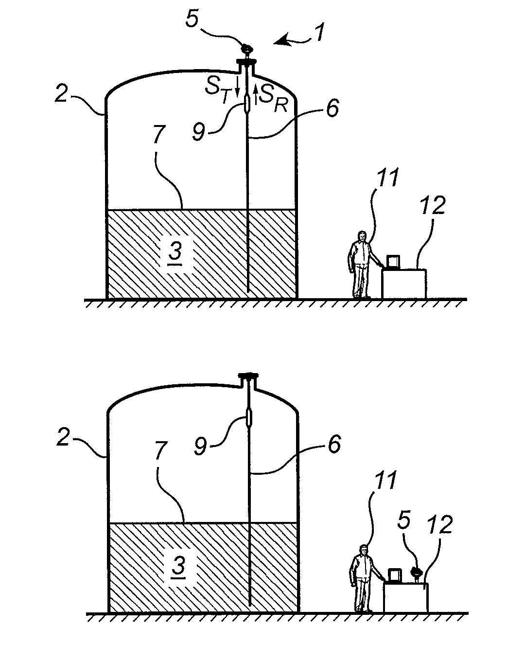
[0057]FIGS. 1b-c illustrate later phases of the verification method according to the present invention, and will be described in further detail below.

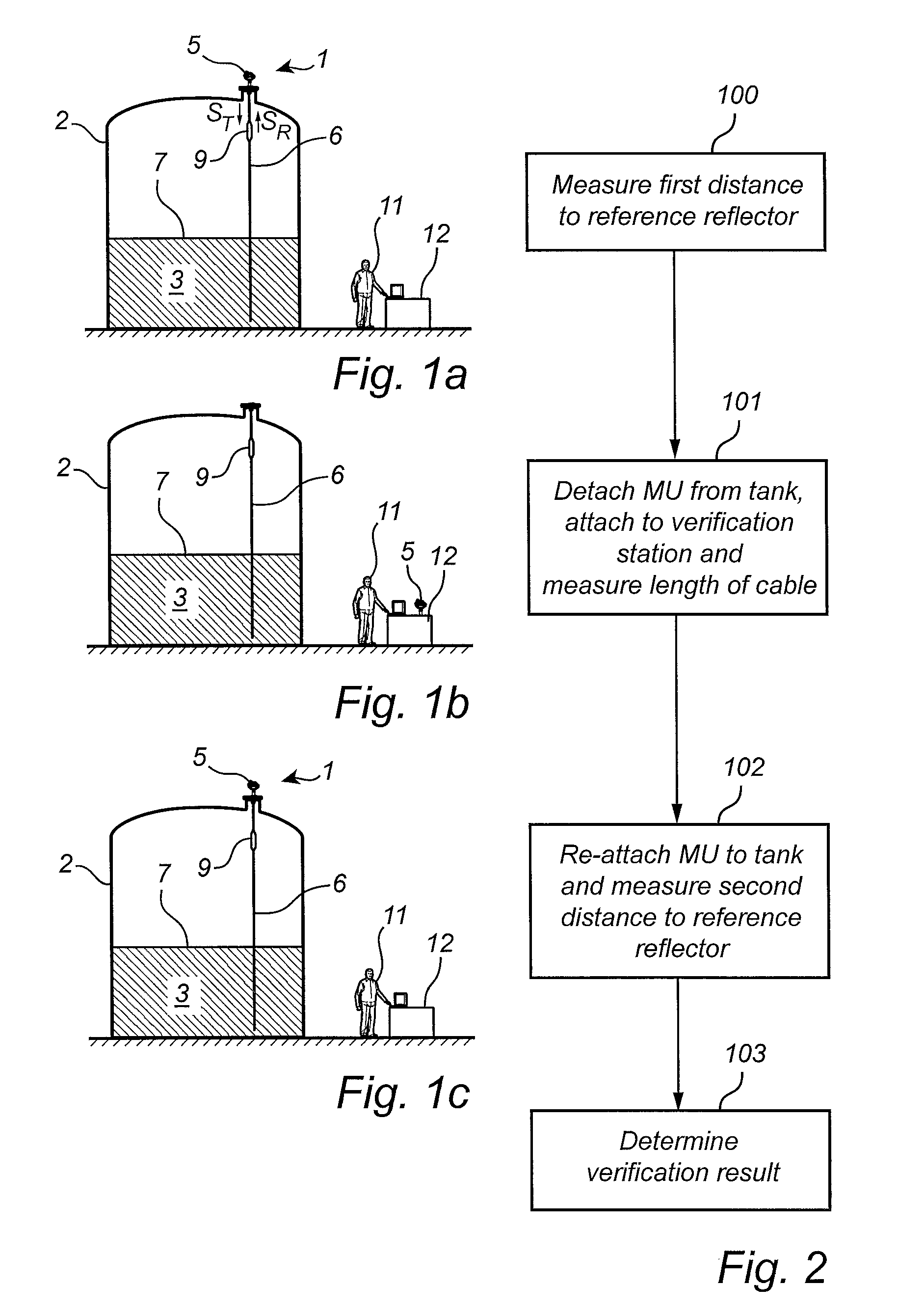
[0058]A first embodiment of the verification method according to the present invention will now be described with reference to FIGS. 1a-c and the flow-chart in FIG. 2.

[0059]In the first step 100, a first distance dRR1 to the reference reflector 9 is measured. This step is carried out with the measurement unit 5 attached to the tank 2 and connected to the transmission line probe 6 as shown in FIG. 1a.

[0060]In the subsequent step 101, the operator 11 detaches the measurement unit 5 from the tank 2, and attaches the measurement unit 5 to the verification station 12. This is schematically illustrated in FIG. 1b. When the measurement unit 5 is attached to the verification station 12, the operator 11 controls the measurement unit 5 to measure an electromagnetic signal propagation property of the verification station 12. This electromagnetic...

second embodiment

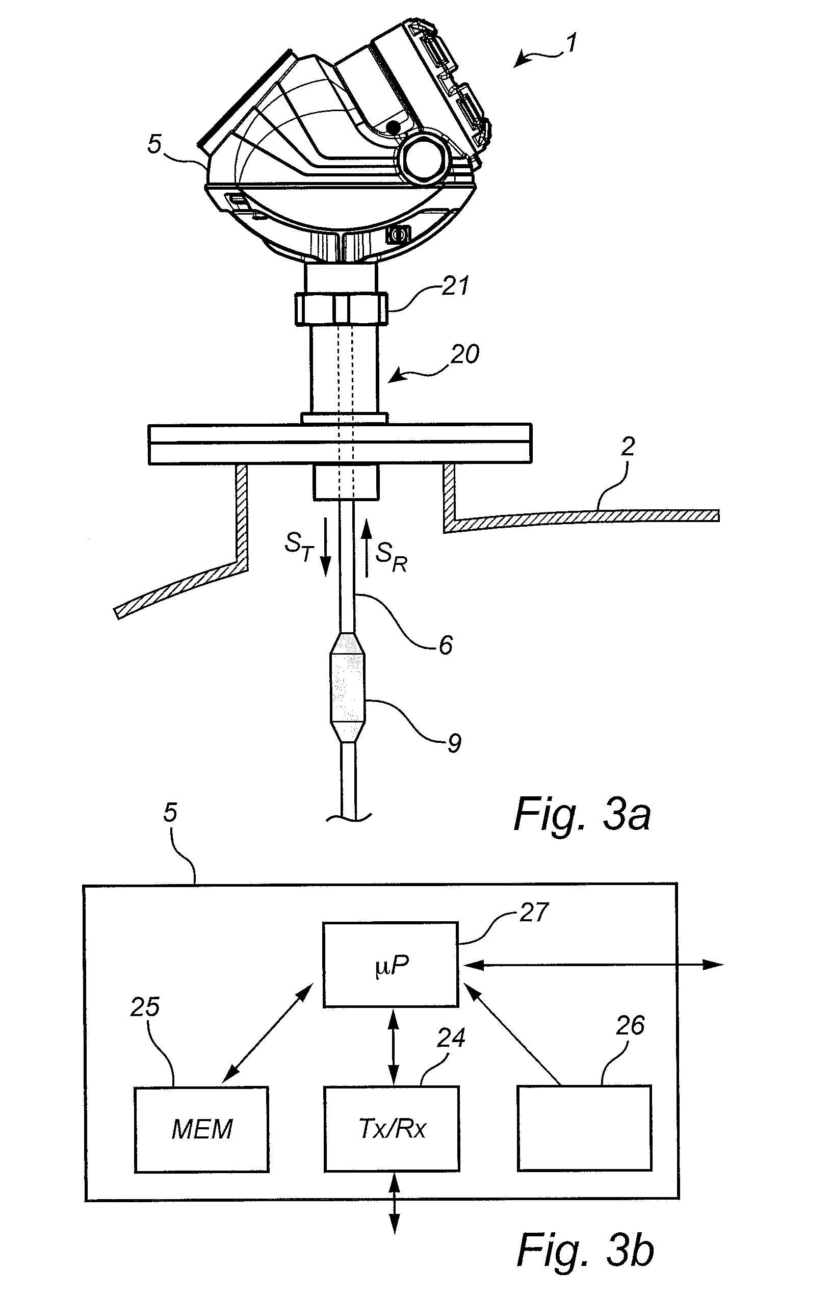
[0068]With reference to FIGS. 4a-b and FIGS. 3a-b, different parts of a verification method according to the present invention will now be described. FIG. 4a is a flow-chart outlining a first part of the method, to be carried out before the measurement unit verification measurement carried out using a verification arrangement as described above in connection with FIGS. 1a-c and FIG. 2, and FIG. 4b is a flow-chart outlining a second part of the verification method, to be carried out after the measurement unit verification measurement.

[0069]Referring to FIG. 4a and FIGS. 3a-b, the first process is initiated by providing the command MRR (Measure Reference Reflector) to the processing unit 27 of the level gauge system 1. In a first step 200, the internal temperature of the measurement unit 5 is measured using the temperature sensor 26 and stored in the memory 25. Subsequently, in step 201, a first distance dRR1 to the reference reflector 9 is measured and stored in the memory 25. Therea...


PUM


Abstract

The present invention relates to a method of verifying a measurement accuracy of a level gauge system. The method comprises determining a first measurement value indicative of a time-of-flight of a first electromagnetic reflection signal to a reference reflector and back; determining a measurement unit verification measurement value based on a response signal from a verification arrangement; determining a second measurement value indicative of a time-of-flight of a second electromagnetic reflection signal to the reference reflector and back; and determining a verification result based on the first measurement value, the second measurement value and the measurement unit verification measurement value. Through embodiments of the present invention, it will be verified that the measurement unit is functioning correctly and that level gauge system works as it should also after being reconnected to the propagation device.

Description

FIELD OF THE INVENTION[0001]The present invention relates to a method of verifying a measurement accuracy of a level gauge system, and to a level gauge system.TECHNICAL BACKGROUND[0002]Radar level gauge (RLG) systems are in wide use for determining the filling level of a product contained in a tank. Radar level gauging is generally performed either by means of non-contact measurement, whereby electromagnetic signals are radiated towards the product contained in the tank, or by means of contact measurement, often referred to as guided wave radar (GWR), whereby electromagnetic signals are guided towards and into the product by a probe acting as a waveguide. The probe is generally arranged to extend vertically from the top towards the bottom of the tank. The probe may also be arranged in a measurement tube, a so-called chamber, that is connected to the outer wall of the tank and is in fluid connection with the inside of the tank.[0003]The transmitted electromagnetic signals are reflect...

Claims


Application Information

Patent Timeline
Patent Type & Authority Patents(United States)
IPC IPC(8): G01S13/08G01F25/00G01S13/88
CPCG01F25/0061G01S13/88G01F23/284G01S7/4052G01S7/4065G01S7/4082G01F25/20G01F25/00
Inventor WIDAHL, CHRISTOFFERLARSSON, MICHAEL
Owner ROSEMOUNT TANK RADAR
Why Eureka
Try Eureka