Rivet setting machine

a rivet setting machine and linear displacement technology, applied in the direction of mechanical measuring arrangements, distance measurement, instruments, etc., can solve the problems of rivet setting cycle, not always as fast as sometimes desired, prior automated control system, etc., to improve direct measurement and accuracy, advantageously more accurate, and faster rivet setting cycle time

Active Publication Date: 2015-05-12
NEWFREY
View PDF224 Cites 9 Cited by
  • Summary
  • Abstract
  • Description
  • Claims
  • Application Information

AI Technical Summary

Benefits of technology

[0005]The present rivet setting machine is advantageous over conventional devices. For example, in one aspect, the present machine, system and method allow for a much faster rivet setting cycle time due to the less complex sensed values and calculations required. Furthermore, the present machine, system and method are advantageously more accurate since a direct linear displacement measurement is employed. Another aspect advantageously mounts the linear displacement sensor adjacent to the nosepiece which improves the direct measurement and accuracy by avoiding multiple component tolerance and movement variations; this provides a direct punch position measurement relative to the nosepiece-clamped workpiece when determining and / or varying a rivet head-to-workpiece flushness condition. Additional advantages and features of the present invention will be apparent from the following description and appended claims taken in conjunction with the accompanying drawings.

Problems solved by technology

While these prior patents have been significant advances in the field, their automated control complexity is not always required for some more simple rivet setting situations.
For example, these prior automated control systems are not always as fast as sometimes desired for each rivet setting cycle due to the many actions being sensed and compared, such as force sensing with a load cell, and electric motor current and / or voltage sensing.

Method used


Image

  • Rivet setting machine
  • Rivet setting machine
  • Rivet setting machine

Examples


Embodiment Construction

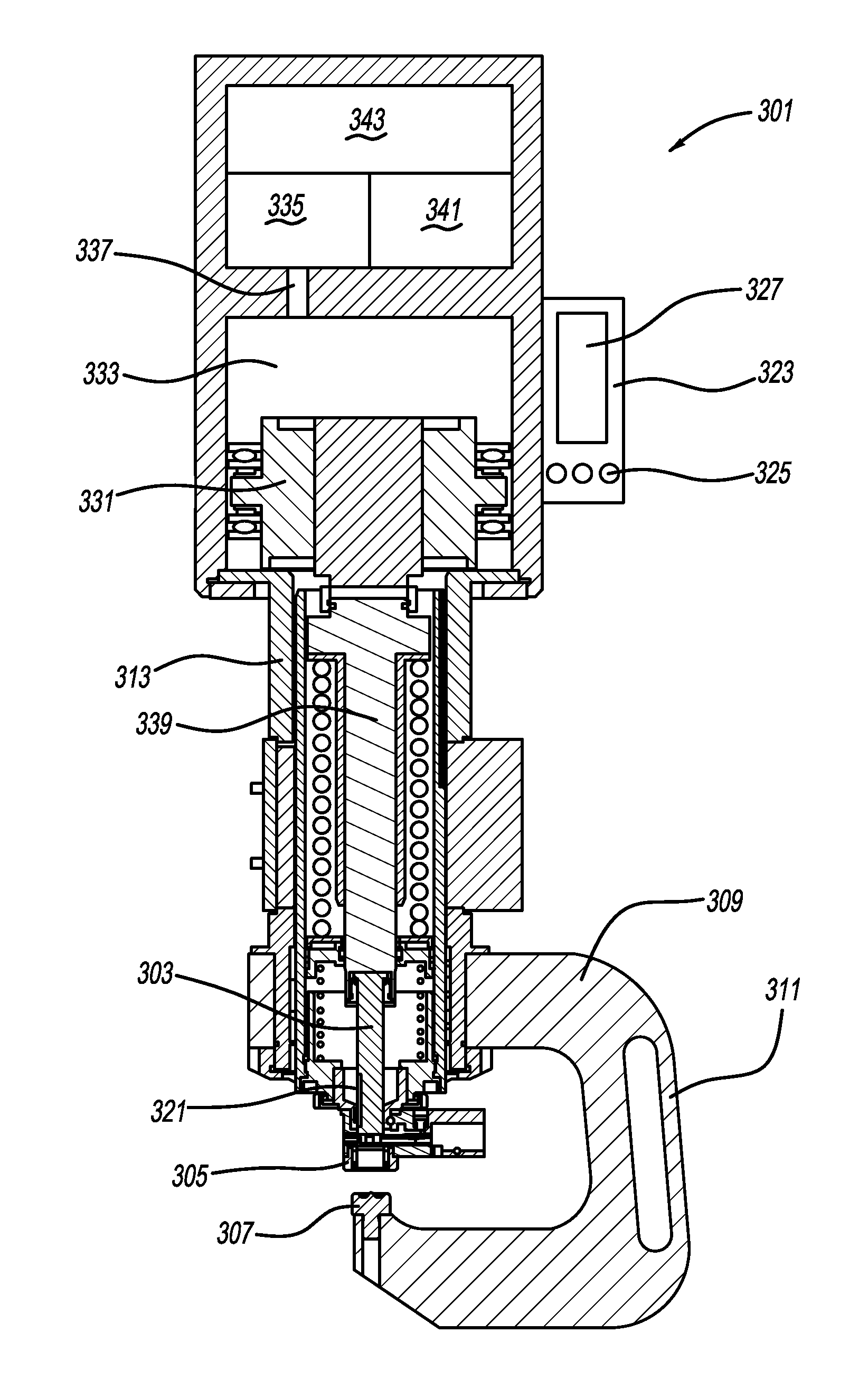
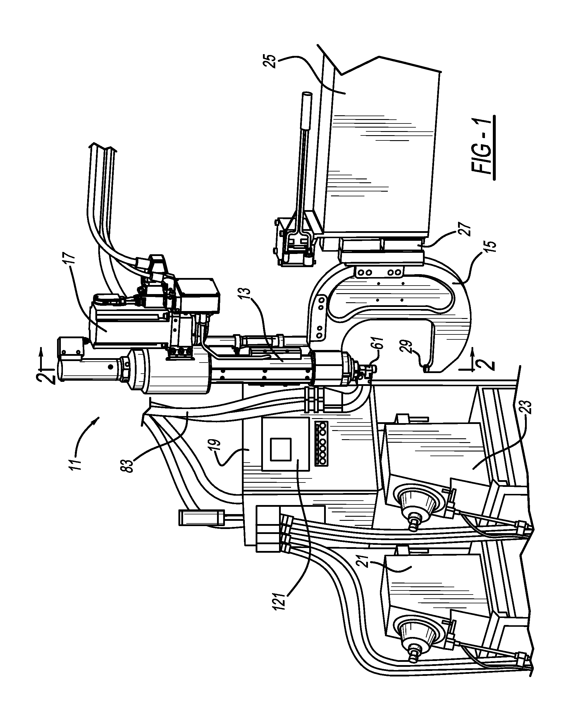
[0015]FIGS. 1-4 illustrate a first embodiment of a rivet setting machine 11 which includes a housing 13, a C-frame 15, an actuator 17, a programmable controller 19, rivet feeders 21 and 23, and an automatically moveable and articulated robot 25. C-frame 15 is coupled to an arm of articulated robot 25 through one or more linear slide mechanisms 27. In turn, one end of C-frame 15 is mounted to housing 13, while an opposite end of C-frame 15 retains a die 29. Housing 13 includes one or more outer protective covers.

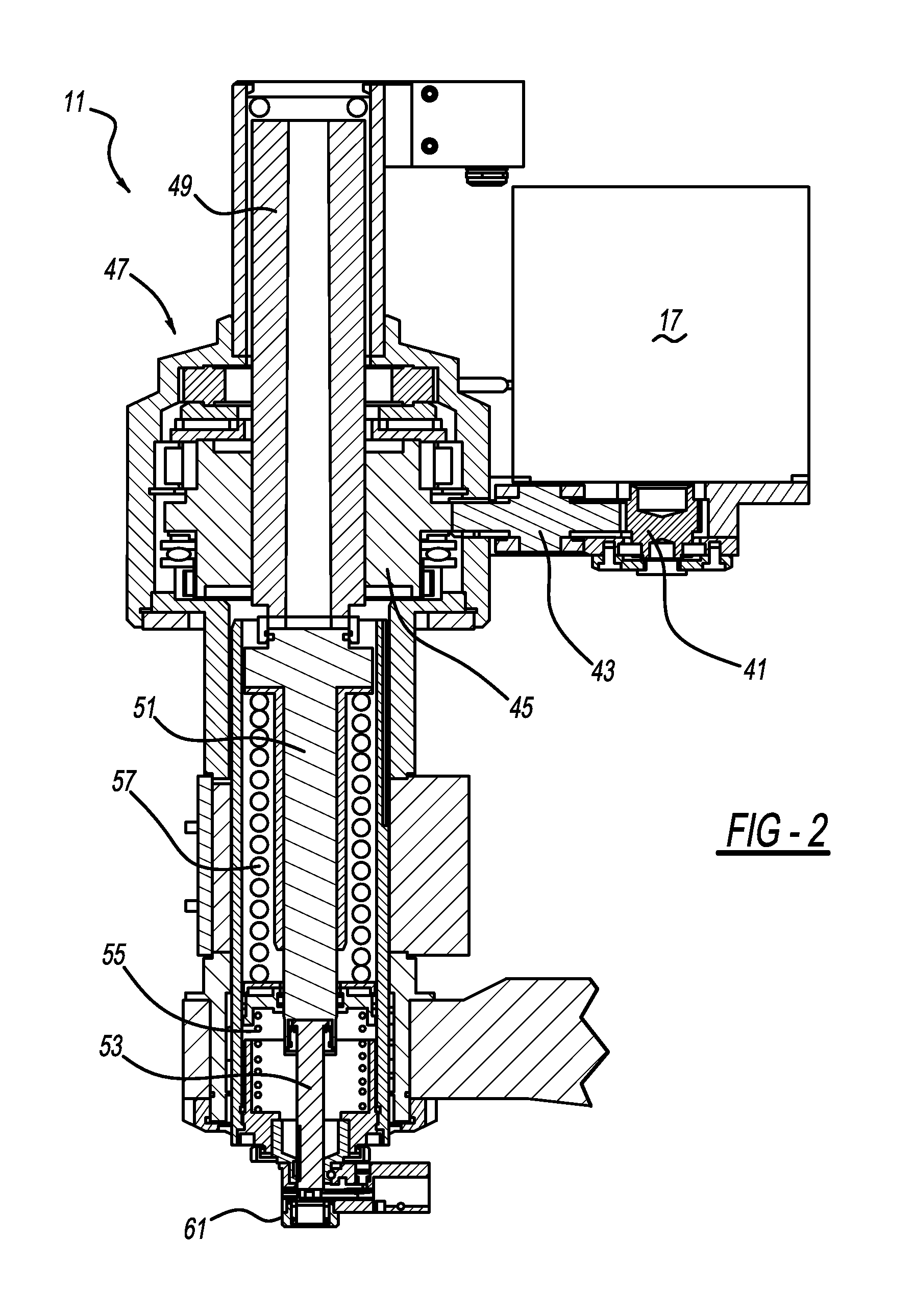
[0016]Actuator 17 is preferably an electric motor which serves to rotate a set of gears 41, 43 and 45 of a power transmission 47. The rotation of gear 45 serves to linearly drive a longitudinally elongated spindle 49 toward and away from die 29 through a threaded interface between gear 45 (also known as a nut) and spindle 49. Additionally, a receiver rod 51 is coupled to a leading end of spindle 49, which in turn, has a punch rod 53, also known as a ram, coupled to the leadin...


PUM

PropertyMeasurementUnit
linear displacement sensoraaaaaaaaaa
magnetic radiant fieldaaaaaaaaaa
current/voltageaaaaaaaaaa

Abstract

A rivet setting machine is provided. In another aspect, a linear displacement sensor directly senses and detects a position of a rivet-setting punch relative to a nosepiece of a rivet setting machine. A further aspect provides a control system and software instructions for sensing the relative position of a punch and nosepiece used by a programmable controller to determine and monitor a rivet setting position without use of a force sensor, motor current / voltage sensor, or a rotation sensor.

Description

BACKGROUND AND SUMMARY[0001]The present disclosure relates generally to rivet setting, and more particularly to linear displacement sensing within a rivet setting machine.[0002]Automated and robotically moved rivet setting machines are known. Exemplary machines for use with self-piercing rivets are disclosed in the following U.S. patents: U.S. Pat. No. 8,146,240 entitled “Riveting System and Process for Forming a Riveted Joint” which issued to Mauer et al. on Apr. 3, 2012; U.S. Pat. No. 7,559,133 entitled “Riveting System” which issued to Chitty et al. on Jul. 14, 2009; and U.S. Pat. No. 6,789,309 entitled “Self-Piercing Robotic Rivet Setting System” which issued to Kondo on Sep. 14, 2004. All of these patents are incorporated by reference herein. While these prior patents have been significant advances in the field, their automated control complexity is not always required for some more simple rivet setting situations. For example, these prior automated control systems are not alwa...

Claims


Application Information

Patent Timeline
Patent Type & Authority Patents(United States)
IPC IPC(8): B21J15/02B21J15/10B21J15/26B21J15/28
CPCB21J15/025B21J15/285B21J15/105B21J15/26B21J15/28Y10T29/49833Y10T29/5343Y10T29/53496Y10T29/5307Y10T29/53065Y10T29/53522Y10T29/49835Y10T29/49837Y10T29/49956Y10T29/5377
Inventor SCHLAFHAUSER, JOSEPH KARL
Owner NEWFREY
Why Eureka
Try Eureka