Latchable module housings and methods of making and using the same

a technology of latching module and housing, which is applied in the field of optical modules, can solve the problems of affecting the deployment and installation of the module, and affecting the stability of the housing and/or its locking mechanism, so as to achieve the effect of reducing the chance of damage to the housing and/or the locking mechanism and minimal force inserted and removed

Active Publication Date: 2015-05-12
SOURCE PHOTONICS
View PDF22 Cites 12 Cited by
  • Summary
  • Abstract
  • Description
  • Claims
  • Application Information

AI Technical Summary

Benefits of technology

[0015]In one aspect, the present invention may include a module housing, generally comprising (a) a chassis, (b) one or more pivots attached to the chassis, (c) a latch configured to secure the chassis and / or housing in a complementary and / or corresponding slot when in a locked position, (d) a slider configured to be in contact with and / or connected to the latch and to move the latch relative to the chassis, the latch and / or the slider configured to move on and / or around the pivot(s), and (e) a handle configured to be in contact with and / or connected to the slider such that when the handle moves from a first position to a second position, the slider and the latch move to one of the locked position and an unlocked position. Because the latch and / or the slider move on or around the pivot(s) attached to the chassis of the module housing, and the handle in positive contact with and / or connected to the slider and / or the latch, the latch is more reliably moved between the unlocked and locked positions.
[0031]The present module housings and methods of manufacturing and using such module housings advantageously provide housings which may be easily seated, securely and reliably locked in a corresponding and / or complementary module socket, and inserted and removed from the module socket with minimal force.

Problems solved by technology

The differences in design may lead to differences in the deployment and installation of the module.
However, removing the module housing when the lever is not in the proper position can damage the tapered end or projection and / or the socket or cage.
If the force applied first does not completely lock or unlock the module housing prior to the second force being applied, the latch, the projection and / or the socket may be damaged.
Consequently, conventional latches may be difficult to properly seat, lock in place and / or remove.
Visual-only inspection can produce intermittent and / or total loss of functionality and / or conductivity because vibrations, connecting cable movement and / or temperature changes may result in unseating of the module if it is not fully locked into position.
Likewise, audible-only verification may result in faulty seating because some modules will emit an audible “click” once seated, while others will click upon actuation of the latching mechanism, but will still require additional force to properly seat the housing.
Generally, and regardless of type of conventional latch, mechanical verification is a relatively time-consuming and cumbersome process, particularly when many modules require installation in a short period of time.
Therefore, mechanical verification is a step that may often be skipped by users when inserting such modules.
Consequently, modules may be improperly installed, may have only intermittent functionality, or may lose functionality entirely, causing interruption and / or failure of the device in which such modules are installed.
Additionally, removal of optical modules from the corresponding sockets may be difficult without causing damage to the latch and / or the module.
If the Mylar tab is pulled too vigorously and / or twisted, the tab can detach from the module thereby causing failure of the mechanism.
If the latch / slider is not in the proper position when the module is removed, the tapered end or projection and / or the socket may be damaged.
However, this release mechanism requires bending of the locking plate and / or the slider to unlock the optical transceiver, thus requiring a relatively high releasing force.
Such operation is inconvenient and places repeated high bending stress on the locking plate and / or the slider.
Other conventional module latches may have similar disadvantages when removing a module from a socket.

Method used


Image

  • Latchable module housings and methods of making and using the same
  • Latchable module housings and methods of making and using the same
  • Latchable module housings and methods of making and using the same

Examples


first embodiment

[0089]In the first embodiment, the handle 313 is rotatably attached to the chassis 309 and comprises arms 313a, a grasping bar (see, e.g., 313b in FIG. 13) and a shaft 330. However, in other embodiments, the handle 313 may be hingedly attached to the chassis 309. In some embodiments the arms 313a, the grasping bar 313b and the shaft 330 may be cast and / or formed as a single piece. In other embodiments, the arms 313a, the grasping bar 313b and the shaft 330 may comprise two or more pieces, fixedly attached to each other (e.g., by screwing, pinning, pressing, crimping, etc.). In some embodiments the arms 313a, the grasping bar 313b and the shaft 330 may be formed from the same material or materials (e.g., when the arms 313a, the grasping bar 313b and the shaft 330 are cast and / or formed as a single piece). In embodiments where the arms 313a, the grasping bar 313b and the shaft 330 comprise two or more pieces, the arms 313a, the grasping bar 313b and the shaft 330 may be formed from di...

second embodiment

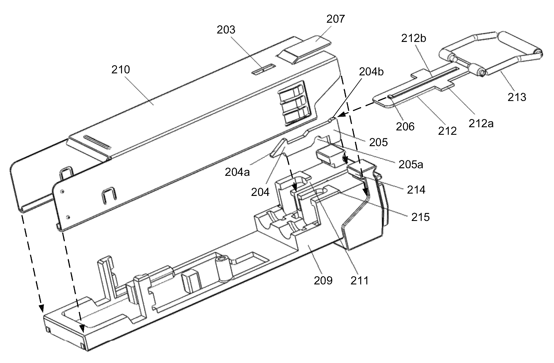
[0105]Referring now to FIGS. 18-21, a third exemplary module housing 500 is shown. Referring initially to FIG. 18 (which shows the module housing 500 with its exterior casing removed for clarity), the module housing 500 comprises (i) a chassis 509, (ii) two pivots 508, (iii) a handle 573 having arms 574a, grasping bar 574b and upper bars 574c, and (iv) a latch / slider 505 located between the two pivots 508 and having a projection 504 and first through third slider pins 416-418. In FIG. 18, the handle 573 is shown in the lowered position, and the latch / slider 505 and the projection 504 in the locked position. Similar to FIG. 12, the latch / slider 505 is configured to move with respect to the chassis 509. However, the third exemplary module housing 500 of FIG. 18 differs from the second exemplary module housing 300 of FIG. 12 in that (i) the module housing 500 comprises two pivots 508 (one on either side of the latch / slider 505, (ii) the latch / slider may comprise a single unitary body (...


PUM

PropertyMeasurementUnit
angleaaaaaaaaaa
angleaaaaaaaaaa
angleaaaaaaaaaa

Abstract

An optical module housing that may be easily seated, locked in and removed from a socket, thereby reducing or eliminating potential damage to the module and socket, and methods for making and using the housing are disclosed. The module housing generally includes a chassis, one or more pivots attached to the chassis, a latch configured to secure the housing in a corresponding slot when in a locked position, a slider configured to be in contact with and / or connected to the latch and to move the latch relative to the chassis, the latch and / or the slider being configured to move on and / or around the pivot(s) and a handle configured to be in contact with and / or connected to the slider such that when the handle moves from a first position to a second position, the slider and latch move to the locked and / or an unlocked positions.

Description

RELATED APPLICATION[0001]This application claims the benefit of Chinese Patent Application No. 201210175558.4, filed on May 31, 2012, which is incorporated herein by reference in its entirety.FIELD OF THE INVENTION[0002]The present invention generally relates to the field of optical modules (e.g., transmitters, receivers, transceivers and / or transponders, etc.) and housings therefor. More specifically, embodiments of the present invention pertain to module housings (such as for a SFP optical transceiver) that are easily and securely locked into sockets or cages configured to accept such module housings, release mechanisms for such module housings, and methods of making and using the same.DISCUSSION OF THE BACKGROUND[0003]Optical modules are used for transmitting optical signals over fibers in optical fiber networks. Common types of optical modules include transmitter modules, receiver modules, transceiver modules and transponder modules. Optical transceivers transform optical signal...

Claims


Application Information

Patent Timeline
Patent Type & Authority Patents(United States)
IPC IPC(8): G02B6/36G02B6/42
CPCG02B6/4261G02B6/4284Y10T29/49826
Inventor WANG, ZILIWAINWRIGHT, WAYNEHEIMBUCH, MARK
Owner SOURCE PHOTONICS
Why Eureka
Try Eureka