Microsystem enabled photovoltaic modules and systems

a photovoltaic module and micro-system technology, applied in photovoltaic supports, pv power plants, lighting and heating apparatus, etc., can solve the problem that the photovoltaic system is not competitive with fossil fuel generated electricity

Active Publication Date: 2015-05-12
NAT TECH & ENG SOLUTIONS OF SANDIA LLC
View PDF20 Cites 33 Cited by
  • Summary
  • Abstract
  • Description
  • Claims
  • Application Information

AI Technical Summary

Problems solved by technology

At present, photovoltaic systems are not co...

Method used


Image

  • Microsystem enabled photovoltaic modules and systems
  • Microsystem enabled photovoltaic modules and systems
  • Microsystem enabled photovoltaic modules and systems

Examples


Embodiment Construction

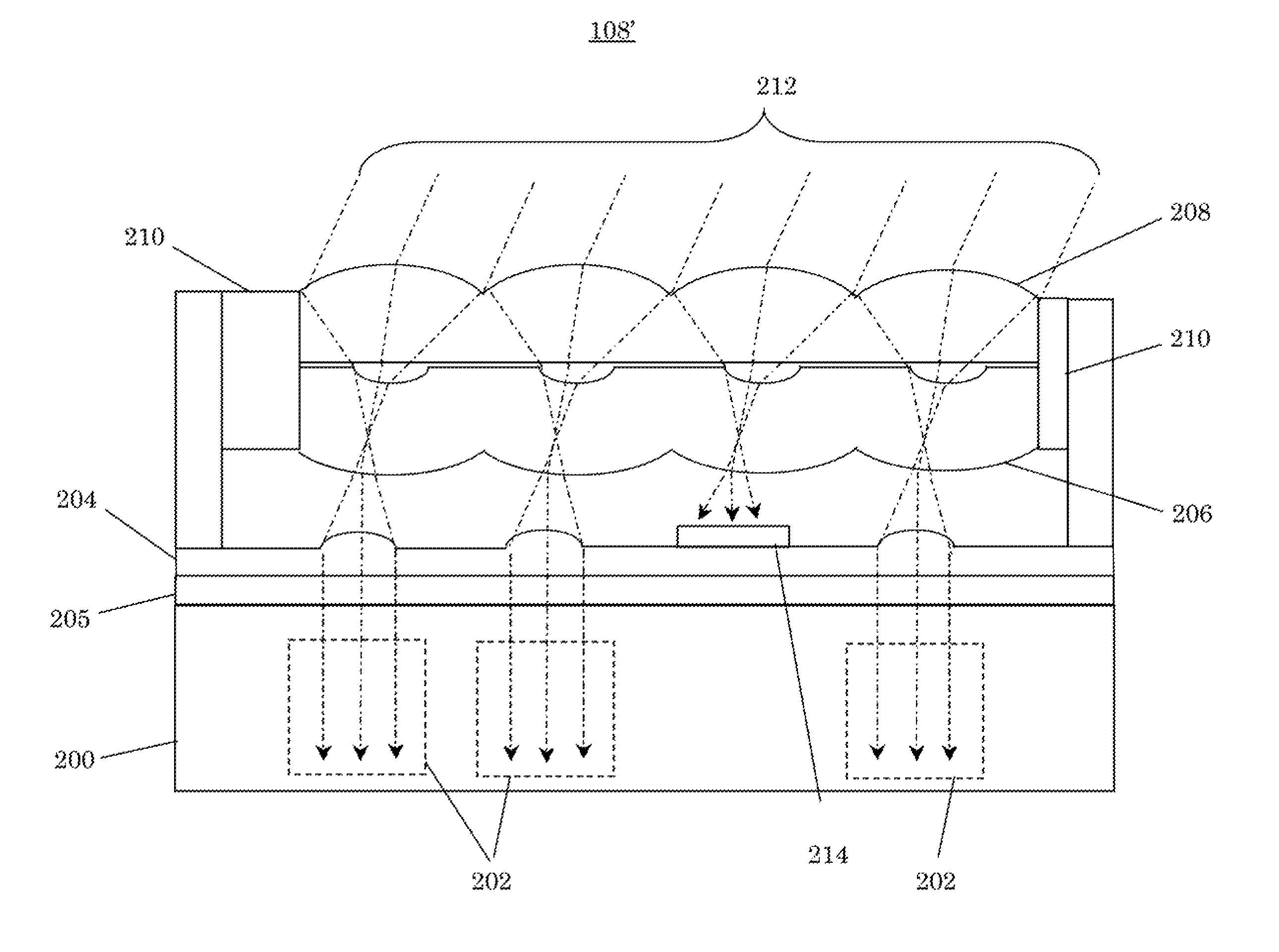
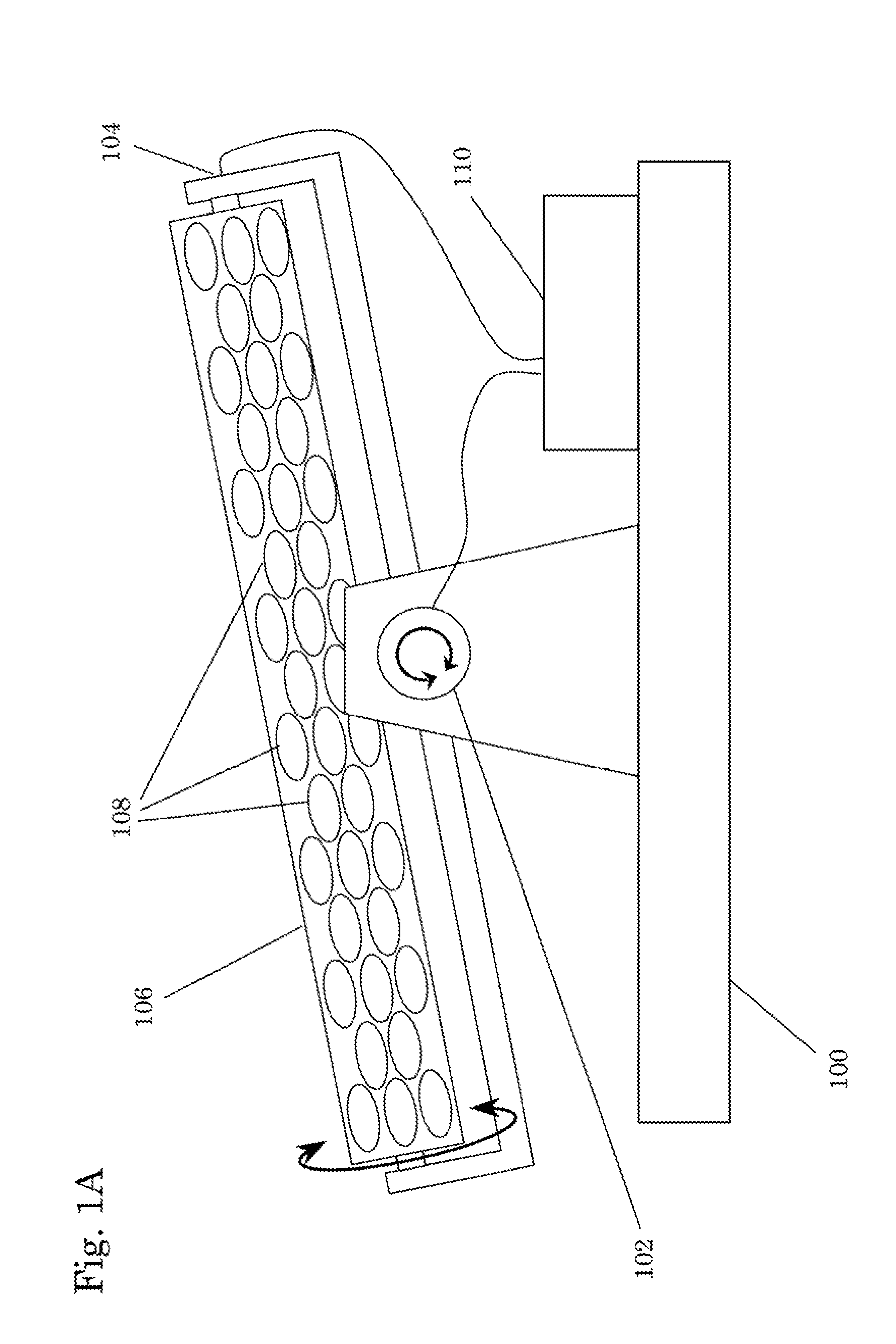
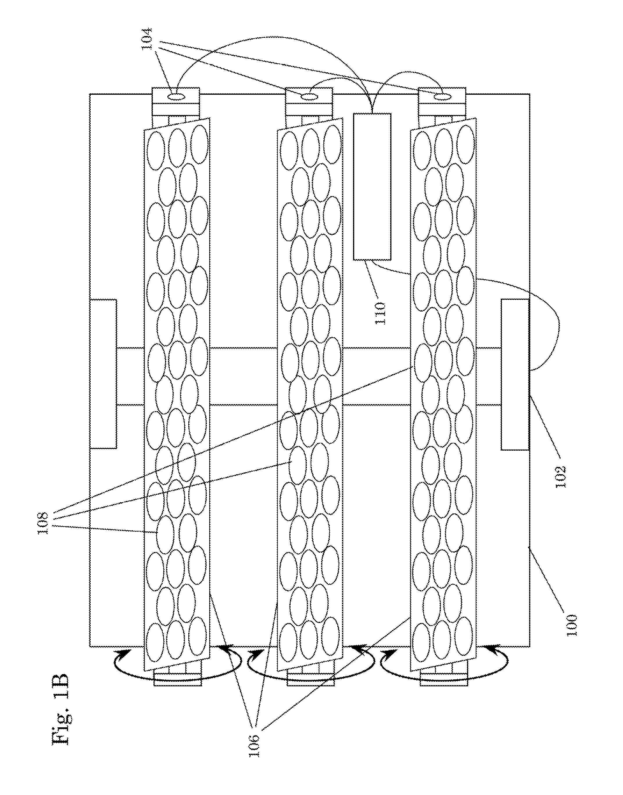
[0018]Exemplary embodiments of the present invention include photovoltaic (PV) solar energy systems that include PV modules that include micro-optical elements to provide for accurate solar tracking. FIGS. 1A and 1B illustrate an exemplary PV solar energy system according to the present invention. FIG. 1A illustrates the exemplary system from a side view and FIG. 1B illustrates the same exemplary system from above.

[0019]The exemplary PV modules used in exemplary PV solar energy system according to the present invention include arrays of individual PV elements. The use of individual PV elements in these exemplary PV modules may help to improve the efficiency and thermal management of the exemplary PV solar energy systems.

[0020]The dimensions of the exemplary micro-optical elements are affected based on the desired size of the PV elements, but are desirably tiled to cover the surface area of the exemplary PV modules as efficiently as possible, typically using either a square or hexago...


PUM


Abstract

A microsystem enabled photovoltaic (MEPV) module including: an absorber layer; a fixed optic layer coupled to the absorber layer; a translatable optic layer; a translation stage coupled between the fixed and translatable optic layers; and a motion processor electrically coupled to the translation stage to controls motion of the translatable optic layer relative to the fixed optic layer. The absorber layer includes an array of photovoltaic (PV) elements. The fixed optic layer includes an array of quasi-collimating (QC) micro-optical elements designed and arranged to couple incident radiation from an intermediate image formed by the translatable optic layer into one of the PV elements such that it is quasi-collimated. The translatable optic layer includes an array of focusing micro-optical elements corresponding to the QC micro-optical element array. Each focusing micro-optical element is designed to produce a quasi-telecentric intermediate image from substantially collimated radiation incident within a predetermined field of view.

Description

[0001]This invention was developed under Contract DE-AC04-94AL85000 between Sandia Corporation and the US. Department of Energy. The U.S. Government has certain rights in this invention.CROSS-REFERENCE[0002]Some or all of the subject matter of this application is related to application Ser. No. 11 / 933,458, titled PHOTOVOLTAIC SOLAR CONCENTRATOR, filed on Nov. 1, 2007, which is hereby incorporated by reference in its entirety.TECHNICAL FIELD[0003]The present invention is directed generally to photovoltaic systems, and, more particularly, to microsystem enabled photovoltaic solar energy modules and systems with integral micro-optics.BACKGROUND OF THE INVENTION[0004]The adoption of photovoltaics for generating electricity from sunlight is largely driven by cost considerations. At present, photovoltaic systems are not competitive with fossil fuel generated electricity. Thus, there is a need to reduce the overall photovoltaic system cost. This entails reducing the cost of photovoltaic mo...

Claims


Application Information

Patent Timeline
IPC IPC(8): H01L31/042H01L31/00F24S23/00H01L31/054
CPCF24J2/06H01L31/054Y02E10/52H02S20/32H01L31/043H01L31/0549H01L31/0547Y02E10/47F24S30/455F24S30/20F24S23/30H01L31/0543
Inventor NIELSON, GREGORY N.SWEATT, WILLIAM C.OKANDAN, MURAT
Owner NAT TECH & ENG SOLUTIONS OF SANDIA LLC
Why Eureka
Try Eureka