
Bandgap reference circuit and regulator circuit with common amplifier

a technology of voltage reference and regulator circuit, which is applied in the direction of power supply lines, instruments, vehicle components, etc., can solve the problems of large power consumption, relatively high implementation cost of the use of these two circuits in tandem as conventional arrangemen

Inactive Publication Date: 2015-05-12
NXP USA INC
View PDF20 Cites 12 Cited by
  • Summary
  • Abstract
  • Description
  • Claims
  • Application Information

AI Technical Summary

Benefits of technology

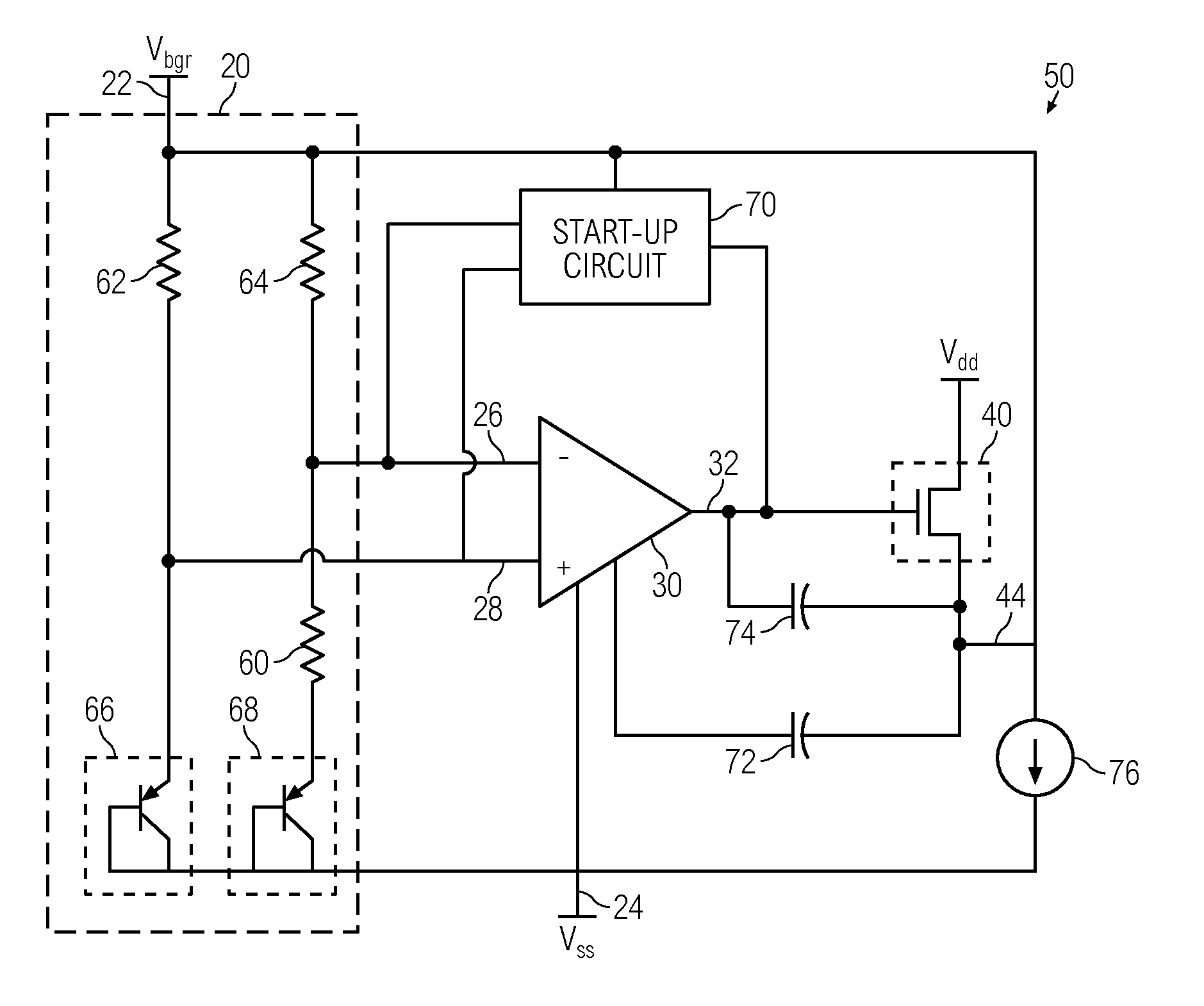
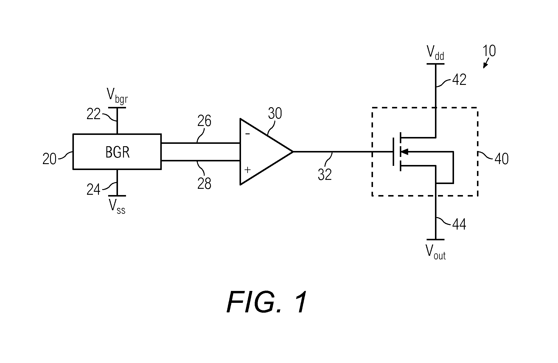
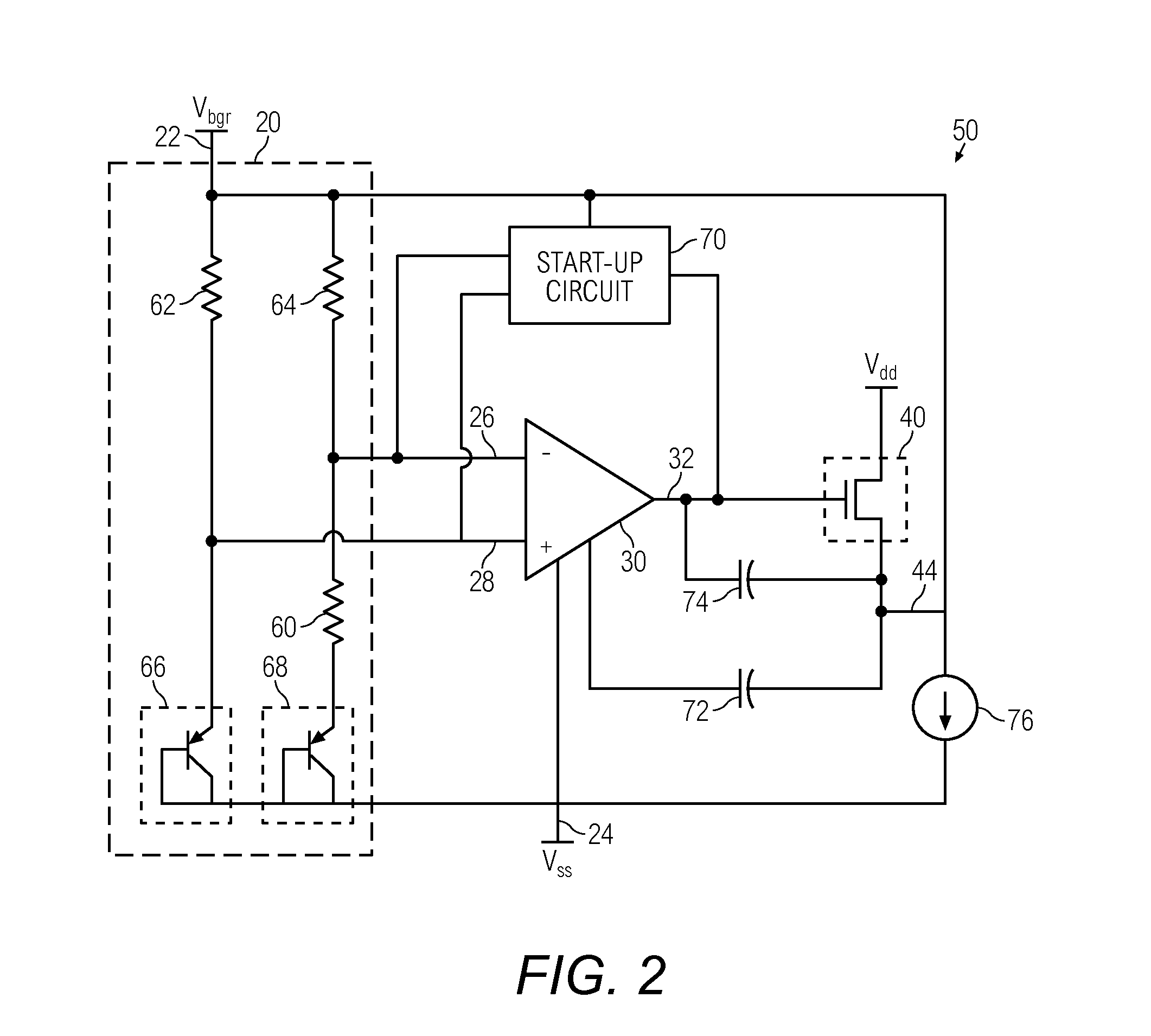
The present invention provides a system that includes a bandgap voltage reference and a voltage regulator circuit that share a common amplifier. This reduces the size and power consumption of the circuit. The system does not require a separate resistor network to bias the output driver transistor, which is typically needed in conventional circuits. The shared amplifier acts as a gain stage for the bandgap voltage reference circuit and an error amplifier for the driver stage of the voltage regulator circuit. The operational amplifier includes an inverted input, a non-inverted input, an output, and a current reference stage. The system provides a stable reference voltage and a stable regulated output voltage, even in low power and space-limited applications.

Problems solved by technology

However, the use of these two circuits in tandem as conventionally arranged is relatively expensive to implement from power and area considerations as the industry demands integrated circuit (IC) designs with ever decreasing power supplies and smaller footprints.
Each circuit occupies valuable circuit area and requires significant power in space-limited and low power applications.

Method used


Image

  • Bandgap reference circuit and regulator circuit with common amplifier
  • Bandgap reference circuit and regulator circuit with common amplifier
  • Bandgap reference circuit and regulator circuit with common amplifier

Examples


Embodiment Construction

[0016]The present invention provides a bandgap voltage reference and voltage regulator system that includes a bandgap voltage reference circuit and a voltage regulator circuit that share a single, common amplifier. The amplifier acts as a gain stage for the bandgap voltage reference circuit and an error amplifier for a driver stage of the voltage regulator circuit. The voltage regulator circuit has an input reference generated by the bandgap voltage reference circuit. The bandgap circuit acts as a load to the driver stage of the regulator circuit, which obviates the need for a bias resistance network, which is typically needed in conventional linear regulators to support the no load condition. The system does not require a resistor network to bias the output driver transistor. Thus, without the need for a resistor network and using a shared amplifier, the area and overall quiescent current are less than those of conventional circuits.

[0017]In one embodiment, the present invention pr...


PUM


Abstract

A bandgap voltage reference and voltage regulator system includes a bandgap voltage reference circuit and a voltage regulator circuit that share a single, common amplifier. The amplifier acts as a gain stage for the reference circuit and as an error amplifier for a driver stage of the regulator circuit. The regulator circuit has an input reference generated by the reference circuit, and the reference circuit acts as a load to the driver stage, obviating the need for a bias resistance network. By sharing the amplifier and obviating the need for a resistance network, the area and overall quiescent current of the system are reduced. The system can be implemented in CMOS / BiCMOS technology and is suited for low power applications.

Description

BACKGROUND OF THE INVENTION[0001]The present invention relates generally to voltage reference and voltage regulator circuits, and more particularly, to a bandgap voltage reference and regulator circuit with a common amplifier.[0002]Voltage references and voltage regulators are electronic circuits that are coextensively used in electronic circuits. Bandgap based voltage references supply a constant and stable reference voltage, typically within the bandgap voltage operating point of 1.2V, to other devices in a circuit such as voltage regulators. Voltage regulators provide a constant voltage, independent of load current, for a predetermined range of load currents.[0003]The bandgap voltage reference typically includes a bandgap core having multiple resistors in combination with multiple transistors and a gain stage to generate the reference voltage equal to the bandgap voltage of the semiconductor material. The voltage regulator receives an input reference voltage generated by the band...

Claims


Application Information

Patent Timeline
Patent Type & Authority Patents(United States)
IPC IPC(8): G05F3/22G05F3/30
CPCG05F3/30Y10S323/901
Inventor GUPTA, RAKESH K.BANERJEE, JAIDEEPWADHWA, SANJAY K.
Owner NXP USA INC
Learn More